Engineering:Pin header


A pin header (or simply, header) is a form of electrical connector. A male pin header consists of one or more rows of metal pins molded into a plastic base, often 2.54 mm (0.1 in) apart, though available in many spacings.[1] Male pin headers are cost-effective due to their simplicity. The female counterparts are sometimes known as female headers (also as pin sockets), though there are numerous naming variations of male and female connectors. Historically, headers have sometimes been called "Berg connectors"[2] or "DuPont" connectors, but headers are manufactured by many companies.[3]
Overview

Normally pin headers are through-hole devices (THD/THT), but surface-mount devices (SMD/SMT) exist too. In the SMD case, the solder side of the pins are bent on a 90-degree angle so as to be soldered to pads on the printed circuit board (PCB). On single row SMD headers the pins are bent alternating to one side or the other, on dual row SMD headers the pins are simply bent outwards. If pin headers are optional, the THD variant is often chosen for ease of manual assembly.
Headers can be either straight (vertical) or right-angle, the latter form is sometimes used to connect two PCBs together horizontally.[1] Most often, headers are available in one or two rows,[1] though three or more rows are available from some manufacturers. They are often sold as long strips (typically 36 / 40 / 50 pins) which can easily be cut apart to a required number of pins. Many pin lengths are available to minimize labor during PCB assembly.
Male pin headers are often associated with ribbon cable connectors.[4] When used alone, they can be recipients of jumpers, which have spacings of 2.54 mm (0.1 in) and 2.00 mm (0.079 in).[5]
Header types can be categorized by their pitch (uniform distance between pins measured from center to center). Some common header pitches are:[1]
- 5.08 mm (0.200 in)
- 3.96 mm (0.156 in)
- 2.54 mm (0.100 in) with 0.64 mm (0.025 in) square pins[6] or precision machined 0.50 mm (0.020 in) round pins[7]
- 2.00 mm (0.079 in) with 0.50 mm (0.020 in) square pins[8]
- 1.27 mm (0.050 in)
- 1.00 mm (0.0394 in)
Shrouded or box header

Pin headers with a plastic guide box around them are known as a shrouded header or box header (BH) and are normally used in combination with insulation-displacement connectors (IDC) for ribbon cables. A square notch (key) in the shroud prevents placing the connector (polarised by a "bump" on one side) the wrong way around.[4] Some are available without the square notch cutout. Others have levers on the ends of the box to allow the attached connector to be removed more easily.
Polarizer key
Some systems polarize or key the pin header connection with something that fills and blocks one of the holes in the sockets.[9][10][11][12] One pin of the wrong pin header (or the correct pin header rotated in the wrong orientation) hits that obstruction and prevents an incorrect connection. The correct pin header has one or more pins in the header removed or clipped to indicate a key for correct orientation.
Keyed connections are very commonly used on computer motherboards, for example those conforming to the ATX standard.
-
 2×5 shrouded header with one pin missing for USB 1.1/2.0 connector expansion from an ATX motherboard.
 -
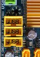
 Standard USB 3.0 / 3.x Gen 1 19-pin shrouded header (20 with one missing).
 -
 USB 9-pin and 19-pin headers.
 -
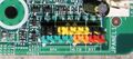 Motherboard front panel connector for PC speaker, power and reset buttons, and power and HDD-activity LEDs.
 -
 Various pin headers on a motherboard (bottom), including HD Audio (keyed 15-pin), front panel, and more.


Pin numbering
In absence of a pin 1 designation on the header, if a designation is missing from the header, the PCB may have a marking indicating orientation (historically, the solder pad around the hole of pin 1 of a THD header is often square rather than round).
For multi-row pin headers, the pin number is more complex, because knowing the location of pin 1 doesn't automatically ensure how the remaining pins are numbered. Typically for headers attached to ribbon cables, the pins are numbered so they go linearly across the cable. Because of the way the connector attaches to the cable, this means in a two-row header, pins in one row have odd numbers and pins in the other row have even numbers.[13]
See also
References
- ↑ 1.0 1.1 1.2 1.3 "Header Term". http://www.interfacebus.com/Glossary-of-Terms_header.html.
- ↑ Brearley, David (2015-10-02). "Breakthrough contact design spawned $500M+ connector company". https://www.connectortips.com/breakthrough-contact-design-spawned-500m-connector-company/.
- ↑ "Header Manufacturer List". http://www.interfacebus.com/connector-header-manufacturers.html.
- ↑ 4.0 4.1 "Shrouded Header Term". http://www.interfacebus.com/Glossary-of-Terms-shrouded-header.html.
- ↑ "Shunts and Jumpers". https://www.samtec.com/connectors/standard-board-to-board/shunts/jumpers.
- ↑ TSW-series 2.54 mm Male Pin Header; Samtec.com
- ↑ "Pitch 2.54_Pin Connectors_Products_Leyconn Electronics Co., ltd.". http://www.leyconn.com/en/index.php/Product-index-cat_id-216.html.
- ↑ TMM-series 2.00 mm Male Pin Header; Samtec.com
- ↑ ""Front panel Connections"". http://www.pcityourself.com/building/frontPanelConnections.php.
- ↑ "USB 3.0 Header to USB 2.0 Header pinout"
- ↑ "Voided Header Pins and Blanked Socket Cavities"
- ↑ Lee Penrod."How to Install Front USB by Connecting Front USB Ports to a Motherboard". Quote: "One pin is blocked so that it is impossible to install improperly."
- ↑ 10 pin IDC male connector diagram and applications pinouts
External links
- Examples
- Headers, ECS
- Headers, Harwin
- Headers & Jumpers, Samtec
- Headers & Jumpers, Tayda
- Headers, Flex Connection
- Headers, Memcon
 |  |
