Servomechanism
This article needs attention from an expert in Engineering. The specific problem is: The article is about a broad subject area in engineering and needs major revision in addition to academic and text book references. (September 2013) |
In mechanical and control engineering, a servomechanism (also called servo system, or simply servo) is a control system for the position and its time derivatives, such as velocity, of a mechanical system. It often includes a servomotor, and uses closed-loop control to reduce steady-state error and improve dynamic response.[1] In closed-loop control, error-sensing negative feedback is used to correct the action of the mechanism.[2] In displacement-controlled applications, it usually includes a built-in encoder or other position feedback mechanism to ensure the output is achieving the desired effect.[3] Following a specified motion trajectory is called servoing,[4] where "servo" is used as a verb. The servo prefix originates from the Latin word servus meaning slave.[1]
The term correctly applies only to systems where the feedback or error-correction signals help control mechanical position, speed, attitude or any other measurable variables.[5] For example, an automotive power window control is not a servomechanism, as there is no automatic feedback that controls position—the operator does this by observation. By contrast a car's cruise control uses closed-loop feedback, which classifies it as a servomechanism.
Applications
Position control

A common type of servo provides position control. Commonly, servos are electric, hydraulic, or pneumatic. They operate on the principle of negative feedback, where the control input is compared to the actual position of the mechanical system as measured by some type of transducer at the output. Any difference between the actual and wanted values (an "error signal") is amplified (and converted) and used to drive the system in the direction necessary to reduce or eliminate the error. This procedure is one widely used application of control theory. Typical servos can give a rotary (angular) or linear output.
Speed control
Speed control via a governor is another type of servomechanism. The steam engine uses mechanical governors; another early application was to govern the speed of water wheels. Prior to World War II the constant speed propeller was developed to control engine speed for maneuvering aircraft. Fuel controls for gas turbine engines employ either hydromechanical or electronic governing.
Others
Positioning servomechanisms were first used in military fire-control and marine navigation equipment. Today servomechanisms are used in automatic machine tools, satellite-tracking antennas, remote control airplanes, automatic navigation systems on boats and planes, and antiaircraft-gun control systems. Other examples are fly-by-wire systems in aircraft which use servos to actuate the aircraft's control surfaces, and radio-controlled models which use RC servos for the same purpose. Many autofocus cameras also use a servomechanism to accurately move the lens. A hard disk drive has a magnetic servo system with sub-micrometer positioning accuracy. In industrial machines, servos are used to perform complex motion, in many applications.
Servomotor

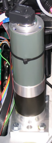
The grey/green cylinder is the brush-type DC motor. The black section at the bottom contains the planetary reduction gear, and the black object on top of the motor is the optical rotary encoder for position feedback.

1. electric motor
2. position feedback potentiometer
3. reduction gear
4. actuator arm
A servomotor is a specific type of motor that is combined with a rotary encoder or a potentiometer to form a servomechanism. This assembly may in turn form part of another servomechanism. A potentiometer provides a simple analog signal to indicate position, while an encoder provides position and usually speed feedback, which by the use of a PID controller allow more precise control of position and thus faster achievement of a stable position (for a given motor power). Potentiometers are subject to drift when the temperature changes whereas encoders are more stable and accurate.
Servomotors are used for both high-end and low-end applications. On the high end are precision industrial components that use a rotary encoder. On the low end are inexpensive radio control servos (RC servos) used in radio-controlled models which use a free-running motor and a simple potentiometer position sensor with an embedded controller. The term servomotor generally refers to a high-end industrial component while the term servo is most often used to describe the inexpensive devices that employ a potentiometer. Stepper motors are not considered to be servomotors, although they too are used to construct larger servomechanisms. Stepper motors have inherent angular positioning, owing to their construction, and this is generally used in an open-loop manner without feedback. They are generally used for medium-precision applications.[6]
RC servos are used to provide actuation for various mechanical systems such as the steering of a car, the control surfaces on a plane, or the rudder of a boat. Due to their affordability, reliability, and simplicity of control by microprocessors, they are often used in small-scale robotics applications. A standard RC receiver (or a microcontroller) sends pulse-width modulation (PWM) signals to the servo. The electronics inside the servo translate the width of the pulse into a position. When the servo is commanded to rotate, the motor is powered until the potentiometer reaches the value corresponding to the commanded position.
History
James Watt's steam engine governor is generally considered the first powered feedback system. The windmill fantail is an earlier example of automatic control, but since it does not have an amplifier or gain, it is not usually considered a servomechanism.
The first feedback position control device was the ship steering engine, used to position the rudder of large ships based on the position of the ship's wheel. John McFarlane Gray was a pioneer. His patented design was used on the SS Great Eastern in 1866. Joseph Farcot may deserve equal credit for the feedback concept, with several patents between 1862 and 1868.[7]
The telemotor was invented around 1872 by Andrew Betts Brown, allowing elaborate mechanisms between the control room and the engine to be greatly simplified.[8] Steam steering engines had the characteristics of a modern servomechanism: an input, an output, an error signal, and a means for amplifying the error signal used for negative feedback to drive the error towards zero. The Ragonnet power reverse mechanism was a general purpose air or steam-powered servo amplifier for linear motion patented in 1909.[9]
Electrical servomechanisms were used as early as 1888 in Elisha Gray's Telautograph.
Electrical servomechanisms require a power amplifier. World War II saw the development of electrical fire-control servomechanisms, using an amplidyne as the power amplifier. Vacuum tube amplifiers were used in the UNISERVO tape drive for the UNIVAC I computer. The Royal Navy began experimenting with Remote Power Control (RPC) on HMS Champion in 1928 and began using RPC to control searchlights in the early 1930s. During WW2 RPC was used to control gun mounts and gun directors.
Modern servomechanisms use solid state power amplifiers, usually built from MOSFET or thyristor devices. Small servos may use power transistors.
The origin of the word is believed to come from the French "Le Servomoteur" or the slavemotor, first used by J. J. L. Farcot in 1868 to describe hydraulic and steam engines for use in ship steering.[10]
The simplest kind of servos use bang–bang control. More complex control systems use proportional control, PID control, and state space control, which are studied in modern control theory.
Types of performances
Servos can be classified by means of their feedback control systems:[11]
- type 0 servos: under steady-state conditions they produce a constant value of the output with a constant error signal;
- type 1 servos: under steady-state conditions they produce a constant value of the output with null error signal, but a constant rate of change of the reference implies a constant error in tracking the reference;
- type 2 servos: under steady-state conditions they produce a constant value of the output with null error signal. A constant rate of change of the reference implies a null error in tracking the reference. A constant rate of acceleration of the reference implies a constant error in tracking the reference.
The servo bandwidth indicates the capability of the servo to follow rapid changes in the commanded input.
See also
- Fractional horsepower motor
- Motion control
- Servo control
- Synchro, a form of transmitter and receiver motor used in servomechanisms
Further reading
- Bennett, S. (1993). A History of Control Engineering 1930–1955. London: Peter Peregrinus Ltd. On behalf of the Institution of Electrical Engineers. ISBN 0-86341-280-7.
- Hsue-Shen Tsien (1954) Engineering Cybernetics, McGraw Hill, link from HathiTrust
References
- ↑ 1.0 1.1 Escudier, Marcel; Atkins, Tony (2019) (in en). A Dictionary of Mechanical Engineering (2 ed.). Oxford University Press. doi:10.1093/acref/9780198832102.001.0001. ISBN 978-0-19-883210-2. http://www.oxfordreference.com/view/10.1093/acref/9780198832102.001.0001/acref-9780198832102.
- ↑ Baldor Electric Company – Servo Control Facts. Accessed 25 September 2013
- ↑ Anaheim Automation: Servo Motor Guide. Accessed 25 September 2013
- ↑ Clarence W. de Silva. Mechatronics: An Integrated Approach (2005). CRC Press. p. 787.
- ↑ BusinessDictionary.com definition . Accessed 25 September 2013
- ↑ "How to drive a servo motor & its industrial applications". https://electronicscomponents.co.uk/how-to-drive-a-servo-motor-its-industrial-application/.
- ↑ Bennett, Stuart (1986-01-01). A History of Control Engineering, 1800–1930. IET. pp. 98–100. ISBN 978-0-86341-047-5. https://books.google.com/books?id=1gfKkqB_fTcC&pg=PA98.
- ↑ Andrew Betts Brown
- ↑ Eugine L. Ragonnet, Controlling Mechanism for Locomotives, U.S. Patent 930,225, Aug. 9, 1909.
- ↑ IEEE Industry Applications Magazine March/April 1996, pg 74
- ↑ G. W. Younkin, Industrial Servo Control Systems – Fundamentals and Applications – Second Edition, Taylor and Francis, 2007.
External links
- Ontario News "pioneer in servo technology"
- Rane Pro Audio Reference definition of "servo-loop"
- Seattle Robotics Society's "What is a Servo?"
- different types of servo motors"
 |


