Engineering:AND-OR-Invert
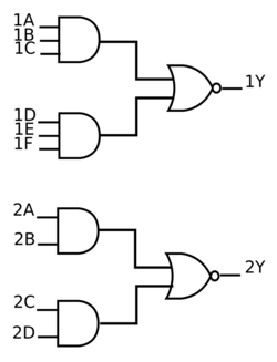
AND-OR-Invert (AOI) logic and AOI gates are two-level compound (or complex) logic functions constructed from the combination of one or more AND gates followed by a NOR gate. Construction of AOI cells is particularly efficient using CMOS technology where the total number of transistor gates can be compared to the same construction using NAND logic or NOR logic. The complement of AOI Logic is OR-AND-Invert (OAI) logic where the OR gates precede a NAND gate.[1]
Overview
Most logic optimization result in a Sum-of-Products or Product-of-Sums logic expression.[2]
AOI is used for Sum-of-Products, the variables are ANDed to form minterms which are ORed together then inverted, such as:
- AB + CD
- ABC + DEF
- ABCD + EFGH
- ABCDE + FGH + JK
- and other variations
Logic operations
AOI gates perform one or more AND operations followed by an OR operation then an inversion.
2-2 AOI gate

The 2-2 AOI gate can be represented by the following boolean equation and truth table:
[math]\displaystyle{ Q=\overline{(A \wedge B) \vee (C \wedge D)} }[/math]
| 2-2 AOI | ||||
| INPUT A B C D |
OUTPUT Q | |||
| 0 | 0 | 0 | 0 | 1 |
| 0 | 0 | 0 | 1 | 1 |
| 0 | 0 | 1 | 0 | 1 |
| 0 | 0 | 1 | 1 | 0 |
| 0 | 1 | 0 | 0 | 1 |
| 0 | 1 | 0 | 1 | 1 |
| 0 | 1 | 1 | 0 | 1 |
| 0 | 1 | 1 | 1 | 0 |
| 1 | 0 | 0 | 0 | 1 |
| 1 | 0 | 0 | 1 | 1 |
| 1 | 0 | 1 | 0 | 1 |
| 1 | 0 | 1 | 1 | 0 |
| 1 | 1 | 0 | 0 | 0 |
| 1 | 1 | 0 | 1 | 0 |
| 1 | 1 | 1 | 0 | 0 |
| 1 | 1 | 1 | 1 | 0 |
2-1 AOI gate
The 2-1 AOI gate can be represented by the following boolean equation and truth table:
[math]\displaystyle{ Q=\overline{ A \vee (B \wedge C)} }[/math]
| 2-1 AOI | |||
| INPUT A B C |
OUTPUT Q | ||
| 0 | 0 | 0 | 1 |
| 0 | 0 | 1 | 1 |
| 0 | 1 | 0 | 1 |
| 0 | 1 | 1 | 0 |
| 1 | 0 | 0 | 0 |
| 1 | 0 | 1 | 0 |
| 1 | 1 | 0 | 0 |
| 1 | 1 | 1 | 0 |
Electronic implementation
AND-OR-INVERT (AOI) and OAI gates can be readily implemented in CMOS circuitry. AOI gates are particularly advantaged in that the total number of transistors (or gates) is less than if the AND, NOT, and OR functions were implemented separately. This results in increased speed, reduced power, smaller area, and potentially lower fabrication cost. For example, a 2-1 AOI gate can be constructed with 6 transistors in CMOS compared to 10 transistors using a 2-input NAND gate (4 transistors), an inverter (2 transistors), and a 2-input NOR gate (4 transistors).
In NMOS logic, the lower half of the CMOS circuit is used in combination with a load device or pull-up transistor (typically a depletion load or a dynamic load).
AOI gates are similarly efficient in transistor–transistor logic (TTL).
- Examples
TTL 7400-series logic family: (in past decades, a number of AOI parts were available in the 7400 family, but currently most are obsolete)
- SN5450 = dual 2-2 AOI gate, one is expandable[4] (SN54 is military version of SN74)
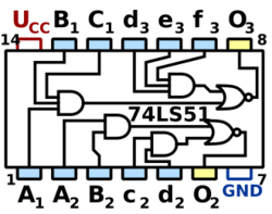
- SN74LS51 = 2-2 AOI gate and 3-3 AOI gate[3]
- SN54LS54 = single 2-3-3-2 AOI gate[5]
CMOS 4000-series logic family:
- CD4085B = dual 2-2 AOI gate[6]
- CD4086B = single expandable 2-2-2-2 AOI gate"[7]
- CD4048B = single expandable 8-input 8-function with three-state output, 8 choices for gate type: 8 NOR / 8 OR / 8 NAND / 8 AND / 4-4 AND-OR-Invert / 4-4 AND-OR / 4-4 OR-AND-Invert / 4-4 OR-AND[8]
See also
References
- ↑ Product of Sums reduction using Karnaugh Map
- ↑ Sum Of Product (SOP) & Product Of Sum (POS)
- ↑ 3.0 3.1 "SN74LS51 Datasheet". 1988. https://www.ti.com/lit/gpn/sn74ls51.
- ↑ "SN5450 Datasheet". 1988. https://www.ti.com/lit/gpn/sn5450.
- ↑ "SN54LS54 Datasheet". 1988. https://www.ti.com/lit/gpn/sn54ls54.
- ↑ "CD4085B Datasheet". 2003. https://www.ti.com/lit/gpn/cd4085b.
- ↑ "CD4086B Datasheet". 2003. https://www.ti.com/lit/gpn/cd4086b.
- ↑ "CD4048B Datasheet". 2003. https://www.ti.com/lit/gpn/cd4048b.
- Tinder, Richard F. (2000). Engineering digital design: Revised Second Edition. pp. 317–319. ISBN 0-12-691295-5. https://books.google.com/books?id=6x0pjjMKRh0C&pg=PT347&lpg=PT347&dq=AOI+gate&source=web&ots=t-wt6hoi1-&sig=dlnF_Kq9jYe27dbr7Rb5gThgM2Y&hl=en&sa=X&oi=book_result&resnum=7&ct=result#PPT346,M1. Retrieved 2008-07-04.
- John, Michael (1997). Application-Specific Integrated Circuits. http://iroi.seu.edu.cn/books/asics/Book2/CH02/CH02.4.htm#pgfId=799. Retrieved 2008-07-04.


