Earth:Trailer connectors in Australia
| Example | Description |
|---|---|
| Socket | |
| Pin |
A number of standards prevail in Australia for trailer connectors, the electrical connectors between vehicles and the trailers they tow that provide a means of control for the trailers.
The Australian market uses its own version of especially the European contacts, but also completely own contacts.[1][2]
The only connector used on the Australian market that is fully ISO standard conformant is the 7-pin ABS / EBS plug.
Since Australia has vehicles from both the North American market and the European market there is a mixture of 12V and 24V.
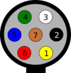
7-pin trailer connector (AS 4735) for heavy duty vehicles
This connector is based on both SAE J560 and ISO 1185 and is providing either 12V, 7 x 40A or 24V, 7 x 20A. The voltage varies from vehicle to vehicle.
| # | DIN | Signal | Color | Rec. cross-section | Notes | |
|---|---|---|---|---|---|---|
| mm² | AWG | |||||
| 1 | 31 | Ground (-) | White | 10 | 8 | |
| 2 | 58 or 58L | Clearance lamps/Outline marker lamps, Side marker lamps, identification lamps | Black | 4 | 12 | |
| 3 | L | Left Turn Signal | Yellow | 4 | 12 | |
| 4 | 54 | Stop lamps | Red | 6 | 10 | |
| 5 | R | Right Turn Signal | Green | 4 | 12 | |
| 6 | 58 or 58R | Tail lamps, registration plate lamp | Brown | 4 | 12 | |
| 7 | Reversing lamps or +12V via ignition lock | Blue | 6 | 10 | ||
Round trailer connectors Type 1
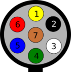
These connectors are based on ISO 1724 in 5-pin and 7-pin versions, but with some difference in the wiring.
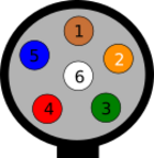
Round 7-pin trailer connector Type 1 (AS 2513)
This contact has chosen to use one of the connections of the ISO 1724 is used for position light to electric brakes (Pin 5, 58R), which means that if you connect a trailer with electric brakes to a towing vehicle wired according to ISO 1724 and turn on the position lights the trailer will be braking. Pin 2 (54G) is in the Australian wiring standard the reversing light, which is a minor problem.
| # | DIN | Signal | Color | Rec. cross-section | Notes | |
|---|---|---|---|---|---|---|
| mm² | AWG | |||||
| 1 | L | Left Turn Signal | Yellow | 1.5 | 15 | |
| 2 | Reversing lamps, control current to block surge brakes when reversing. | Black | 1.5 | 15 | ||
| 3 | 31 | Ground connected to chassis | White | 2.5 | 13 | |
| 4 | R | Right Turn Signal | Green | 1.5 | 15 | |
| 5 | Electric brake control | Blue | 1.5 | 15 | ||
| 6 | 54 | Stop lamps | Red | 1.5 | 15 | |
| 7 | 58 | Tail lamps, clearance lamps/outline marker lamps and registration plate lamp left side | Brown | 1.5 | 15 | |
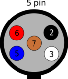
Round 5-pin trailer connector Type 1
This connector is replaced by the 7-pin (AS 2513), but can be found on older vehicles. Note that pins 1 and 4 missing. Pin placement is identical to the 7-pin ISO 1724 with the absence of these pins. This means that you can connect a trailer with a 5-pin connector to a 7-pin socket or the other way around, but since the pins are wired in a different way the result may be far from what was expected.
| # | DIN | Signal | Color | Rec. cross-section | Notes | |
|---|---|---|---|---|---|---|
| mm² | AWG | |||||
| 2 | L | Left Turn Signal | Yellow | 1.5 | 15 | |
| 3 | 31 | Ground | White | 2.5 | 13 | |
| 5 | R | Right Turn Signal | Green | 1.5 | 15 | |
| 6 | 54 | Stop lamps | Red | 1.5 | 15 | |
| 7 | 58 | Tail lamps, clearance lamps/outline marker lamps and registration plate lamp | Brown | 1.5 | 15 | |
Round trailer socket type 2
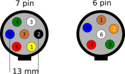
Round 7 pin trailer connector type 2
| # | DIN | Signal | Color | Rec. cross-section | Notes | |
|---|---|---|---|---|---|---|
| mm² | AWG | |||||
| 1 | L | Left Turn Signal | Yellow | 1.5 | 15 | |
| 2 | Reversing lamps | Pink | 1.5 | 15 | ||
| 3 | 31 | Ground | White | 2.5 | 13 | |
| 4 | R | Right Turn Signal | Green | 1.5 | 15 | |
| 5 | Electric brake control | Blue | 1.5 | 15 | ||
| 6 | 54 | Stop lamps | Red | 1.5 | 15 | |
| 7 | 58 | Tail lamps, clearance lamps/outline marker lamps and registration plate lamp | Brown | 1.5 | 15 | |
Round 6-pin trailer connector type 2
| # | DIN | Signal | Color | Rec. cross-section | Notes | |
|---|---|---|---|---|---|---|
| mm² | AWG | |||||
| 1 | 58 | Tail lamps, clearance lamps/outline marker lamps and registration plate lamp right side | Brown | 1.5 | 15 | |
| 2 | L | Left Turn Signal | Yellow | 1.5 | 15 | |
| 3 | R | Right Turn Signal | Green | 1.5 | 15 | |
| 4 | 54 | Stop lamps | Red | 1.5 | 15 | |
| 5 | Electric brake control | Blue | 1.5 | 15 | ||
| 6 | 31 | Ground (-) for pin 1 - 8 | White | 2.5 | 13 | |
Rectangular trailer connectors Type 3
| # | DIN | Signal | Color | Rec. cross-section | Notes | |
|---|---|---|---|---|---|---|
| mm² | AWG | |||||
| 1 | L | Left Turn Signal | Yellow | 1.5 | 15 | |
| 2 | Reversing lamps, control current to block surge brakes when reversing. | Black | 1.5 | 15 | ||
| 3 | 31 | Ground | White | 2.5 | 13 | |
| 4 | R | Right Turn Signal | Green | 1.5 | 15 | |
| 5 | Electric brake control | Blue | 1.5 | 15 | ||
| 6 | 54 | Stop lamps | Red | 1.5 | 15 | |
| 7 | 58 | Tail lamps, clearance lamps/outline marker lamps and registration plate lamp | Brown | 1.5 | 15 | |
| 8 | 30 | +12V permanent | Orange | 2.5 | 13 | |
| 9 | 15 | +12V via ignition lock | Pink | 2.5 | 13 | |
| 10 | 31 | Ground | White | 2.5 | 13 | |
| 11 | Rear fog lamps | Grey | 1.5 | 15 | ||
| 12 | Spare | Purple | 2.5 | 13 | ||
The image of the 7 and 12 pin flat plugs are from the cable entry view (and possibly the images of the round connectors too). Please see reference [2] (VSB1 section 14) for front image. Reference [1] Narva wiring diagrams also have the diagrams cable entry view. If you want the front view images in colour see [3]
References
- ↑ "NARVA Wiring Diagrams". http://www.narva.com.au/products/browse/wiring-diagrams.
- ↑ "Vehicle Standards Bulletin VSB1, Technical Requirements, 14. Electrical Wiring". http://www.infrastructure.gov.au/roads/vehicle_regulation/bulletin/vsb1/vsb_01_b.aspx#14.
- ↑ "Flat 7 pin and 12 pin wiring colour codes". Archived from the original on 2014-06-27. https://archive.is/20140627142843/http://www.rvsupertramp.com.au/Default.aspx?tabid=258.


