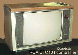
Engineering:Colortrak
Colortrak was a trademark used on several RCA color televisions beginning in the 1970s and lasting into the 1990s. After RCA was acquired by General Electric in 1986, GE began marketing sets identical to those from RCA. GE sold both RCA and GE consumer electronics lines to Thomson SA in 1988. RCA televisions with the Colortrak branding were mid-range models; positioned above the low-end XL-100 series but below the high-end Dimensia and Colortrak 2000 series. RCA discontinued the Colortrak name in the late 1990s, with newer models badged as the Entertainment Series.
Design quirks
During the early 1980s, RCA responded to increased demand for component televisions with monitor capabilities by adding composite and S-video inputs to the Colortrak lineup. These inputs allowed owners to easily connect a stereo audio/video source, like a Video Cassette Recorder, LaserDisc player, or with use of an RCA SelectaVision CED videodisc player to the television. For example, early composite video-equipped RCA sets were to coincidentally be tuned to Non-broadcast channel 91 to display a composite video signal, if a set was equipped with more than one input, subsequent inputs are designated to channels 92 to 95, which are usually accessed from the remote control. Later models abandoned this design, favoring A/V inputs which were accessible by pressing the channel up/down buttons, or A/V inputs which were controlled by their own button.
Tuner Issues
After Thomson SA acquired the GE and RCA brand names, they began designing a new chassis for RCA and GE televisions, which debuted in 1993 models. Instead of using a tuner module soldered to the circuit board, Thomson decided to integrate the tuner into the board itself. Due to the heating and cooling cycles of the circuit board and tuner from normal use, the solder connections between the tuner and the board would fail, causing an intermittent picture or no signal from the coaxial connector. This is easily repairable by desoldering the tuner shield and re-flowing new solder to each connection inside.[1]
See also
References
- ↑ "Repair of a 1993 RCA Colortrak 26" cabinet model TV using the CTC177 chassis". radiotvphononut. 10 May 2013. https://www.youtube.com/watch?v=cnQxGrd-nnA.
 |


