Engineering:Fibre satellite distribution

Fibre satellite distribution is a technology that enables satellite TV signals from an antenna to be distributed using an optical fibre cable infrastructure and then converted to electrical signals for use with conventional set-top box receivers.
Particularly applicable to satellite TV distribution systems in a multi-dwelling unit, such as a block of flats (but useful in smaller domestic distribution systems too), such a hybrid fibre/electrical system reduces the cabling required, reduces signal noise and interference, and provides for an easy upgrade to increase the number of tuners connected at each dwelling.[1]
Conventional systems that distribute the electrical satellite IF signal via a star network of coaxial cable require one relatively short cable run from the central distribution equipment to each tuner connected to the system, whereas in a fibre system, cables can be very long, and split at successive locations, in a tree structure without detriment to the reception.
Advantages
The primary benefit of using optical fibre for a satellite TV IF distribution system is that the fibre can carry the entire received spectrum on one cable, which can then be split to provide for multiple tuners, without requiring a separate feed from the antenna to each tuner. Additional outlets can be added to increase the number of receivers within one home without accessing the central antenna or main infrastructure.
Fibre cable is cheap in long run, retailing at about twice the price of equivalent copper coaxial cable, but replacing four runs of coaxial cable with a single fibre cable. It is also much smaller than the coaxial signal cable used for electrical IF distribution, but robust and flexible. The losses in a fibre system are almost negligible so very long cable runs of hundreds of metres are possible without any signal reinforcement.
Because the signal is carried as a beam of light, it is impervious to the electrical interference that even the best coaxial satellite cable may suffer, and cables can be safely and conveniently run alongside mains power cables. Power consumption is also lower than an equivalent electrical system.[2] [3] [4]
Development
While optical fibre has been used for telephone and Internet backbone data, and even for television and multimedia carriage for terrestrial cable, for many years, use for satellite IF distribution has been held back by considerations of cost and installation convenience.
However, since about 2007, UK company, Global Invacom (which also markets domestic and communal satellite reception and distribution equipment, including SCR single cable distribution equipment) has developed a low cost standardised system of optical fibre distribution suitable for domestic installations and small or medium commercial communal dish systems.[5]
The development was assisted by Astra satellite operator SES both with advice and financial support in the form of the prize for the Astra Innovation Contest run by Astra in 2007, which Global Invacom won for the proposal and initial development of optical fibre distribution systems for satellite TV.[6]
How it works
The complete spectrum of Ku-band satellite reception stretches from 10.70 GHz-12.75 GHz across two signal polarisations, or a bandwidth of about 4000 MHz. This cannot be carried on a single coaxial cable and so in a conventional satellite reception system, just one of four sub-bands (received in vertical and horizontal polarization, and high and low frequency,) is sent from the antenna to the indoor receiver as 0.95 GHz-2.15 GHz IF. Which sub-band is required is signalled from the receiver to the antenna’s LNB by a 13/18V and 0/22 kHz tone on the LNB supply sent up the same coaxial cable. In a single antenna distribution system, special quattro LNB supplies all four sub-bands at once, from four outputs and these are supplied as required to each of the multiple outlets connected to an IF multiswitch.[7]
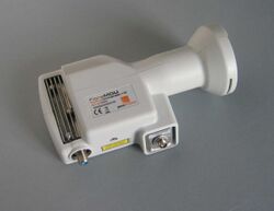
In an optical fibre system at the LNB the four sub-bands are "stacked" in frequency, one above the other, at 0.95 GHz-3.0 GHz (the whole frequency range received in vertical polarisation) and 3.4 GHz-5.45 GHz (horizontal polarisation) and transmitted together as a modulated optical signal down the fibre cable using a 1310 nm semiconductor laser.
The losses in the cable are extremely small (in the region of 0.3dB/km) and the Global Invacom optical LNB output can be split up to 32 ways with a cable length of up to 10 km between the LNB and the receiver.
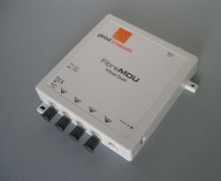
At, or near, the receiver, the optical signal is converted back to the traditional electrical signal with a virtual multiswitch, providing one or more outputs that “appear” to the receiver as a conventional LNB.[8]
Practical considerations
Although the hybrid optical fibre/electrical system provides many advantages over electrical IF distribution to widespread or complex systems, it also requires a new approach by installers familiar only with electrical installations.
The single mode fibre cables use an 8μm fibre armoured with a steel wrap and Kevlar strands inside a plastic jacket. Fibre cable cannot be easily joined (an expensive fusion splicer is required for reliable joints) but pre-made cables with FC type screw-on connectors (mechanically similar in use, but smaller, to the F-connectors used for electrical satellite IF) are available in lengths from 1m to 100m. The same connectors are used on all the optical components of a system, including the optical LNB, splitters, cable joiners, virtual LNB units, etc.
The cables must be properly prepared (the end of the fibre itself cleaned) before connections are made and provision must be made to attenuate the LNB signal, to avoid overloading the receiver, if it is not split between receivers as there is so little attenuation inherent in the cable.
The optical LNB requires two cables connected – the fibre signal cable and a separate F-connector cable to supply the 12V supply to power the LNB electronics. If the installation is a conversion from an electrical system to fibre, an existing redundant coaxial signal cable can be used for the power supply.
See also
References
- ↑ "Giving co-ax the axe" What Satellite & Digital TV (April, 2009) p130-131
- ↑ "Fibre Optic Solutions". Triax. Archived from the original on April 11, 2010. https://web.archive.org/web/20100411061443/http://www.triax.co.uk/Products/Fibre%20Optic%20Solutions.aspx. Retrieved January 13, 2010.
- ↑ SAT Fibre Optics Triax. May 2016 Retrieved October 27, 2017
- ↑ Global Invacom Optical LNB: The Satellite Reception Revolution Tele-Satellite August 2009 Retrieved December 31, 2016
- ↑ "Fibre optic distribution products information". Global Invacom. http://globalinvacom.com/products/fibremdu-virtual-converters.php. Retrieved January 13, 2010.
- ↑ "Global Communications, Invacom, And Era Technology Winners of the SES ASTRA Innovation Contest" (Press release). SES ASTRA. September 28, 2007. Retrieved January 26, 2012.
- ↑ Bains, Geoff. "Installing Home IF Distribution" What Satellite & Digital TV (June, 2007) p47-51
- ↑ "FibreMDU Optical LNB". Global Invacom. http://www.globalinvacom.com/products/fibreopticlnb2.php. Retrieved January 12, 2010.
External links
 |


