Physics:Magnetic gear
A magnetic gear resembles the traditional mechanical gear in geometry and function, using magnets instead of teeth. As two opposing magnets approach each other, they repel; when placed on two rings the magnets will act like teeth. As opposed to conventional hard contact backlash in a spur gear, where a gear may rotate freely until in contact with the next gear, the magnetic gear has a springy backlash. As a result magnetic gears are able to apply pressure no matter the relative angle. Although they provide a motion ratio as a traditional gear, such gears work without touching and are immune to wear of mating surfaces, have no noise, and may slip without damage.
A magnetically coupled gear can be used in a vacuum without lubrication, or operations involving hermetically sealed barriers. This can be an advantage in explosive or otherwise hazardous environments where leaks constitute a real danger.
Design
Magnetic gear systems typically use permanent magnets. They may also use electromagnets for specialized cases including changeable gear ratio. Magnetic gear coupling can be configured in several ways.
Parallel input and output axes, similar to spur gears, have magnetic attraction or repulsion between cogs, such as the north pole magnets on the driving gear attracting the south pole magnets of driven gear or north pole cogs on a driving gear tending to center between north pole cogs of the driven gear. The cogs may be inter meshed to improve coupling.
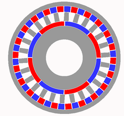
Another configuration is In-line axes that use "flux coupling". A stationary intermediate ferromagnetic cylinder allows a motion ratio due to the harmonic relationship between the number of poles input compared to output. There is no equivalent mechanical gear system, since the two rotating gears are physically isolated from each other and only interact magnetically.
In addition, there are "cycloidal drive" gears with a gear ratio similar to planetary drives, also called "epicyclic" or "eccentric" gears.
Magnetic gears advantages:
- Leak proof mechanical coupling
- Shear / overload proof mechanical coupling
- Wear is limited to bearings, not mating contact surfaces of gears
- Interchangeable ratios either electronically or mechanically in minutes not hours.
The magnetic gear is a magnetic coupling device that renders a mechanical ratio between two magnetically-coupled devices such that:
- They have a ratio of rotation or translational movement between input and output which may be unity in the case of a pure magnetic coupling or one of many gear ratios in a magnetic gearbox.
- They have a torque or traction limiting factor based on the magnetic coupling force.
- They have no physical contact between the main driving and driven elements.
A magnetic gear is composed of magnets of the type permanent, electromagnetic or otherwise magnetically induced fields. It consists of two or more elements that are usually rotating but can be linear or curve linear in nature.
The classical gear is defined as a ratio of pole pairs. Where the Pole pairs are magnets N-S and S-N in nature. For the ratio to be affected there must be at least two elements. with Magnetic pole pair pieces.
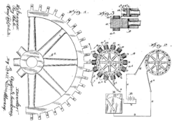
Such devices were invented Armstrong, C. G., 1901, “Power Transmitting Device”, U.S. Pat. No. 0,687,292[1] and developed further from the 1940s[2][3]
Gearing modes
There are four basic magnetic gearing modes.
First-order device
A defined ratio of magnets on one driving element and one driven element, exactly like normal gears. First order gears can be implemented at angles, and through non-magnetic barriers, because they do not require a coupler component.
Second-order device
Second order magnetic gears use a ratio of magnetic pole pairs between inner and outer magnetic rotors, where the rotor with fewer magnets rotates at a higher rate than the rotor with more magnets. An intermediate ferromagnetic pole "stator" is usually held stationary between the rings, to direct the concentration of the magnetic lines between the high speed rotor and the low speed rotor. The gear ratio between the rotors is the number of magnetic pole pairs on the high speed rotor to the number of magnetic pole pairs on the low speed rotor. Since the number of pole pairs is twice the number of magnets, there must be an even number of magnets on both rotors. The Ferromagnetic stator allows for two alternative modes. The first uses the sum of the number of pole pairs of the two rotors as the number of ferromagnetic stator rods, which will drive the secondary rotor the opposite direction of rotation of the primary. The second mode has the number of stator pieces equal the difference between the pole pair counts of the rotors, which drives the secondary rotor the same direction as the primary. The table below shows the relationship between magnets in the rotors, the number of pairs, the number of iron stator rods, the gear ratio and the output direction for a pair of imaginary motors.
| Low Speed Magnets | Low Speed Pairs | High Speed Magnets | High Speed Pairs | Iron Stator Pieces | Gear Ratio | Direction |
|---|---|---|---|---|---|---|
| 20 | 10 | 14 | 7 | 17 | 10:7 | Opposite to input |
| 20 | 10 | 14 | 7 | 3 | 10:7 | Same as input |
Third-order device
A rotational device, where a mode 2 device is modified to have external field coil(s). The external coils create a harmonic flux when powered with multiple phase AC, which behaves like a variable number of stator rods- thus effecting a variable transmission or variable ratio magnetic gear. This type of gear consumes approximately 25% of its input power in the process, causing current in the external coils. This renders the variable magnetic gearbox to less than 75% efficiency, below the typical efficiency of most gear sets. The lower maintenance and the torque limiting characteristics may find suitability in some applications, however.
Fourth-order device
The mode 4 device is a modification to the mode 3 device where a low torque variable speed input, a high torque mechanical input, and a high torque mechanical output. As with the mode 3 device, it consumes approximately 25% of the energy to supply the variable input, however if the variable input is held stationary the device functions as a mode 2 device. Such a device can be termed a torque multiplier.
References
- Krasil'nikov, A. Ya. Krasil'nikov, A. A., 2008, “Calculation of the Shear Force of Highly Coercive Permanent Magnets in Magnetic Systems With Consideration of Affiliation to a Certain Group Based on Residual Induction”, Chemical and Petroleum Engineering, Vol. 44, Nos. 7-8, p. 362-65
- Furlani, E. P., 2001, “Permanent Magnet and Electromechanical Devices”, Academic Press, San Diego.
- Lorimer, W., Hartman, A., 1997, “Magnetization Pattern for Increased Coupling in Magnetic Clutches”, IEEE Transactions on Magnetics, Vol. 33, No. 5, September 1997
- Armstrong, C. G., 1901, “Power Transmitting Device”, U.S. Pat. No. 0,687,292
- Neuland, A. H., 1916, “Apparatus for Transmitting Power”, U.S. Pat. No. 1,171,351
- Faus, H. T., 1940, “Magnet Gearing”, U.S. Pat. No. 2,243,555
- Reese, G. A., 1967, “Magnetic Gearing Arrangement”, U.S. Pat. No. 3,301,091
- Schlaeppi, H. P., 1968, “Magnetic Gears”, U.S. Pat. No. 3,382,386
- Liang, N., 1972, “Magnetic Transmission”, U.S. Pat. No. 3,645,650
- Mabe, Jr., W. J., 1991, “Magnetic Transmission”, U.S. Pat. No. 5,013,949
- Storaasli, A.G., 2016, "Eccentric Magnetic Gear System Based On Repulsion", U.S. Pat. No 9,337,712
- Ackermann, B., Honds, L., 1997, “Magnetic drive arrangement comprising a plurality of magnetically cooperating parts which are movable relative to one another”, U.S. Pat. No. 5,633,555
- Yao, Y., Lee, C., Wang, S., Huang, D., 2000, “Method of designing optimal bi-axial magnetic gears and system of the same”, U.S. Pat. No. 6,047,456
- Furlani, E. P., 2000, “Analytical analysis of magnetically coupled multipole cylinders”, J. Phys. D: Appl. Phys., Vol. 33, No. 1, p. 28-33.
- Jorgensen, F. T., Andersen, T. O., Rasmussen P. O., 2005, “Two dimensional model of a permanent magnet spur gear”, Conf. Record of the 2005 IEEE Industry Applications Conference, p. 261-5
- Krasil'nikov, A. Ya. Krasil'nikov, A. A., 2009, “Torque Determination for a Cylindrical Magnetic Clutch”, Russian Engineering Research, Vol. 29, No. 6, pp. 544–47
- Kyung-Ho Ha, Young-Jin Oh, Jung-Pyo Hong, 2002, “Design and Characteristic Analysis of Non-Contact Magnet Gear for Conveyor by Using Permanent Magnet”, Conf. Record of the 2002 IEEE Industry Applications Conference, p. 1922–27
- General Electric DP 2.7 Wind Turbine Gearbox, http://www.gedrivetrain.com/insideDP27.cfm, referenced June 2010
- Neugart PLE-160, One-Stage Planetary Gearbox, http://www.neugartusa.com/ple—160_gb.pdf, referenced June 2010
- Boston Gear 221S-4, One-stage Helical Gearbox, http://www.bostongear.com/pdf/product_sections/200_series_helical.pdf, referenced June 2010
- Atallah, K., Howe, D. 2001, “A Novel High-Performance Magnetic Gear”, IEEE Transactions On Magnetics, Vol. 37, No. 4, July 2001, p. 2844–46
- Charpentier, J. F., Lemarquand, G., 2001, “Mechanical Behavior of Axially Magnetized Permanent-Magnet Gears”, IEEE Transactions on Magnetics, Vol. 37, No. 3, May 2001, p. 1110–17
- Xinhua Liu, K. T. Chau, J. Z. Jiang, Chuang Yu, 2009, “Design and Analysis of Interior-magnet Outer-rotor Concentric Magnetic Gears”, Journal of Applied Physics, Vol. 105
- Mezani, S., Atallah, K., Howe, D., 2006, “A high-performance axial-field magnetic gear”, Journal of Applied Physics Vol. 99
- Cheng-Chi Huang, Mi-Ching Tsai, Dorrell, D. G., Bor-Jeng Lin, 2008, “Development of a Magnetic Planetary Gearbox”, IEEE Transactions on Magnetics, Vol. 44, No. 3, p. 403-12
- Jorgensen, F. T., Andersen, T. O., Rasmussen, P. O. “The Cycloid Permanent Magnetic Gear”, IEEE Transactions on Industry Applications, Vol. 44, No. 6, November/December 2008, p. 1659–65
- Atallah, K., Calverley, S. D., D. Howe, 2004, “Design, analysis and realisation of a high-performance magnetic gear”, IEE Proc.-Electr. Power Appl., Vol. 151, No. 2, March 2004
- Jian, L., Chau, K. T., 2010, “A Coaxial Magnetic Gear With Halbach Permanent-Magnet Arrays”, IEEE Transactions on Energy Conversion, Vol. 25, No. 2, June 2010, p. 319-28
- Linni Jian, K. T. Chau, Yu Gong, J. Z. Jiang, Chuang Yu, Wenlong Li, 2009, “Comparison of Coaxial Magnetic Gears With Different Topologies”, IEEE Transactions on Magnetics, Vol. 45, No. 10, October 2009, p. 4526-29
- Correlated Magnetics Research, 2010, Company Website, http://www.correlatedmagnetics.com
- Jae Seok Choi, Jeonghoon Yoo, Shinji Nishiwaki, and Kazuhiro Izui, 2010, “Optimization of Magnetization Directions in a 3-D Magnetic Structure”, IEEE Transactions on Magnetics, Vol. 46, No. 6, June 2010, p. 1603–06
- K. T. Chau, Dong Zhang, J. Z. Jiang, Linni Jian, 2008, “Transient Analysis of Coaxial Magnetic Gears Using Finite Element Comodeling”, Journal of Applied Physics, Vol. 103
- Furlani, E. P., 1996, “Analysis and optimization of synchronous magnetic couplings”, J. Appl. Phys., Vol. 79, No. 8, p. 4692
- Bassani, R., 2007, “Dynamic Stability of Passive Magnetic Bearings”, Nonlinear Dynamics, V. 50, p. 161-68
- Tsurumoto, K., 1992, “Basic Analysis on Transmitted Force of Magnetic Gear Using Permanent Magnet”, IEEE Translation Journal on Magnetics in Japan, Vol 7, No. 6, June 1992, p. 447-52
External links
- Correlated Magnetics Research, 2009, Online Video, “Innovative Magnetics Research in Huntsville”, https://www.youtube.com/watch?v=m4m81JjZCJo
- Correlated Magnetics Research, 2009, Online Video, “Non-Contact Attachment Utilizing Permanent Magnets”, https://www.youtube.com/watch?v=3xUm25CNNgQ
 |


