Earth:Electrical resistance survey

Electrical resistance surveys (also called earth resistance or resistivity survey) are one of a number of methods used in archaeological geophysics, as well as in engineering geological investigations. In this type of survey electrical resistance meters are used to detect and map subsurface archaeological features and patterning.
Overview
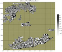
Electrical resistance meters can be thought of as similar to the Ohmmeters used to test electrical circuits. Archaeological features can be mapped when they are of higher or lower resistivity than their surroundings. A stone foundation might impede the flow of electricity, while the organic deposits within a midden might conduct electricity more easily than surrounding soils. Although generally used in archaeology for planview mapping, resistance methods also have a limited ability to discriminate depth and create vertical profiles (see Electrical resistivity tomography). Further applications include the measurement of the electrical resistivity of concrete to determinate the corrosion potential in concrete structures. Electrical resistance surveying is one of the most popular geophysical methods thanks to the fact it is a nondestructive and economically favorable investigation.[1]
Instrumentation
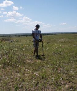
In most systems, metal probes (electrodes) are inserted into the ground to obtain a reading of the local electrical resistance. A variety of probe configurations are used, most having four probes, often mounted on a rigid frame. In these systems, two of the probes, called current probes, are used to introduce a current (either direct or low-frequency switching current) into the earth. The other two probes, called voltage or potential probes, are used to measure the voltage, which indicates the local resistivity. In general, greater probe spacings yield greater depth of investigation, but at the cost of sensitivity and spatial resolution.[2]
Early surveys (beginning in the mid 20th century) often used the Wenner array, which was a linear array of four probes. These were arranged current-voltage-voltage-current, at equal distances across the array. Probes were mounted on a rigid frame, or placed individually. While quite sensitive, this array has a very wide span for its depth of investigation, leading to problems with horizontal resolution. A number of experimental arrays attempted to overcome the shortcomings of the Wenner array, the most successful of these being the twin-probe array, which has become the standard for archaeological use. The twin-probe array - despite its name - has four probes: one current and one voltage probe mounted on a mobile frame to collect survey readings, and the other current probe placed remotely along with a voltage reference probe. These fixed remote probes are connected to the mobile survey probes by a trailing cable. This configuration is very compact for its depth of investigation, resulting in superior horizontal resolution.[3] The logistical advantage of the more compact array is somewhat offset by the trailing cable.
A disadvantage of the systems described above is a relatively slow rate of survey. One solution to this has been wheeled arrays. These use spiked wheels or metal disks as electrodes, and may use a square array (a variation of the Wenner array) to avoid the encumbrance of a trailing cable. Wheeled arrays may be towed by vehicles or by human power.[4]
Systems having long linear arrays of many electrodes are often used in geological applications, and less commonly in archaeology. These take repeated measurements (often computer controlled) using different electrode spacings at multiple points along the extended line of electrodes.[5] Data collected in this way may be used for tomography, or generating vertical profiles.[6]
Capacitively coupled systems that do not require direct physical contact with the soil have also been developed. These systems are capable of tomographic studies as well as mapping horizontal patterning. They may also be used on hard or very dry surfaces that preclude electrical contact necessary for probe resistance systems. While these show promise for archaeological applications, currently available systems operating on this principle lack sufficient spatial resolution and sensitivity. [7][8]
Data collection
Survey usually involves walking with the instrument along closely spaced parallel traverses, taking readings at regular intervals. In most cases, the area to be surveyed is staked into a series of square or rectangular survey "grids" (terminology can vary). With the corners of the grids as known reference points, the instrument operator uses tapes or marked ropes as a guide when collecting data. In this way, positioning error can be kept to within a few centimeters for high-resolution mapping. Early surveys recorded readings by hand, but computer controlled data logging and storage are now the norm.[9]
See also
Further reading
- Schmidt, Armin (2013). Earth Resistance for Archaeologists. Lanham: AltaMira Press.
A general overview of geophysical methods in archaeology can be found in the following works:
- Clark, Anthony J. (1996). Seeing Beneath the Soil. Prospecting Methods in Archaeology. London, United Kingdom: B.T. Batsford Ltd..
- Gaffney, Chris; Gater, John (2003). Revealing the Buried Past: Geophysics for Archaeologists. Stroud, United Kingdom: Tempus.
Notes and references
- ↑ Amini, Amin; Ramazi, Hamidreza (2017-03-02). "CRSP, numerical results for an electrical resistivity array to detect underground cavities" (in en). Open Geosciences 9 (1): 13–23. doi:10.1515/geo-2017-0002. ISSN 2391-5447. Bibcode: 2017OGeo....9....2A. http://www.degruyter.com/view/j/geo.2017.9.issue-1/geo-2017-0002/geo-2017-0002.xml.
- ↑ Clark, Anthony J. (1996). Seeing Beneath the Soil. Prospecting Methods in Archaeology. London, United Kingdom: B.T. Batsford Ltd.
- ↑ Clark, Anthony J. (1996). Seeing Beneath the Soil. Prospecting Methods in Archaeology. London, United Kingdom: B.T. Batsford Ltd.
- ↑ "Historic England: Geophysical Survey in Archaeological Field Evaluation". https://www.historicengland.org.uk/images-books/publications/geophysical-survey-in-archaeological-field-evaluation/.
- ↑ Broken Weblink
- ↑ Cardimona, Steve. "Electrical Resistivity Techniques for Subsurface Investigation". http://www.dot.ca.gov/hq/esc/geotech/gg/geophysics2002/061cardimona_resistivity_overview.pdf.
- ↑ Benjamin Godber of Delisle Catholic science college of Leicestershire
- ↑ Toby Lerone Marseilles University of science speciality (Balamory)
- ↑ Clark, Anthony J. (1996). Seeing Beneath the Soil. Prospecting Methods in Archaeology. London, United Kingdom: B.T. Batsford Ltd.
 |


