Parallel breadth-first search
The breadth-first-search algorithm is a way to explore the vertices of a graph layer by layer. It is a basic algorithm in graph theory which can be used as a part of other graph algorithms. For instance, BFS is used by Dinic's algorithm to find maximum flow in a graph. Moreover, BFS is also one of the kernel algorithms in Graph500 benchmark, which is a benchmark for data-intensive supercomputing problems.[1] This article discusses the possibility of speeding up BFS through the use of parallel computing.
Serial breadth-first search
In the conventional sequential BFS algorithm, two data structures are created to store the frontier and the next frontier. The frontier contains all vertices that have the same distance (also called "level") from the source vertex, these vertices need to be explored in BFS. Every neighbor of these vertices will be checked, some of these neighbors which are not explored yet will be discovered and put into the next frontier. At the beginning of the BFS algorithm, a given source vertex s is the only vertex in the frontier. All direct neighbors of s are visited in the first step, which form the next frontier. After each layer-traversal, the "next frontier" is switched to the frontier and new vertices will be stored in the new next frontier. The following pseudo-code outlines the idea of it, in which the data structures for the frontier and next frontier are called FS and NS respectively.
1    define bfs_sequential(graph(V,E), source s):
2        for all v in V do
3            d[v] = -1;
4        d[s] = 0; level = 1; FS = {}; NS = {};
5        push(s, FS);
6        while FS !empty do
7            for u in FS do
8                for each neighbour v of u do
9                    if d[v] = -1 then
10                       push(v, NS);
11                       d[v] = level;
12           FS = NS, NS = {}, level = level + 1;
First step of parallelization
As a simple and intuitive solution, the classic Parallel Random Access Machine (PRAM) approach is just an extension of the sequential algorithm that is shown above. The two for-loops (line 7 and line 8) can be executed in parallel. The update of the next frontier (line 10) and the increase of distance (line 11) need to be atomic. Atomic operations are program operations that can only run entirely without interruption and pause.
However, there are two problems in this simple parallelization. Firstly, the distance-checking (line 9) and distance-updating operations (line 11) introduce two benign races. The reason of race is that a neighbor of one vertex can also be the neighbor of another vertex in the frontier. As a result, the distance of this neighbor may be examined and updated more than one time. Although these races waste resource and lead to unnecessary overhead, with the help of synchronization, they don't influence the correctness of BFS, so these races are benign. Secondly, in spite of the speedup of each layer-traversal due to parallel processing, a barrier synchronization is needed after every layer in order to completely discover all neighbor vertices in the frontier. This layer-by-layer synchronization indicates that the steps of needed communication equals the longest distance between two vertices, O(d), where O is the big O notation and d is the graph diameter.
This simple parallelization's asymptotic complexity is same as sequential algorithm in the worst case, but some optimizations can be made to achieve better BFS parallelization, for example:
- Mitigating barrier synchronization. Barrier synchronization is necessary after each layer-traversal to ensure the correctness of parallel BFS. As a result, reducing the cost of barrier synchronization is an effective way to speed up parallel BFS.
- Load-balancing for neighbor discovering. Because there is a barrier synchronization after each layer-traversal, every processing entity must wait until the last of them finish its work. Therefore, the parallel entity which has the most neighbors decides the time consumption of this layer. With the optimization of load-balancing, the time of layer-traversal can be reduced.
- Improving the locality of memory references. In parallel system with distributed memory, remote memory reference are getting data from other processing entities, which has usually extra communication cost compared to local memory reference. Thus, local memory reference is faster than remote memory reference. By designing a better data structure or improving the organization of data can lead to more local memory references and reduce the communications needed for remote memory references.
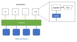
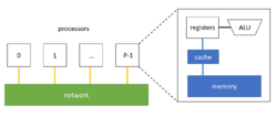
Compared to parallel BFS with distributed memory, shared memory provides higher memory-bandwidth and lower latency. Because all processors share the memory together, all of them have the direct access to it. Thus, the developers don't need to program message passing process, which is necessary for distributed memory to get data from remote local memory. Therefore, the overhead of messages is avoided.[2]
However, the number of vertices in each layer and the number of neighbors of each vertex are shown to be highly irregular, which leads to highly irregular memory accesses and work distribution of BFS. In parallel BFS, this feature reduces the benefits from parallelization due to unbalanced load. As a result, it is very important to make the parallel BFS on shared memory load-balanced. Moreover, exploring the data-locality can also speed up parallel process.
Many parallel BFS algorithms on shared memory can be divided into two types: container centric approaches and vertex centric approaches.[3] In the container centric approach, two data structures are created to store the current frontier and the next vertex frontier. The next vertex frontier is switched to the current frontier at the last of each step. There is a trade-off between the cost for synchronization and data locality according to the place where the data is stored. These two data structures can be held in every processing entity (such as thread) which supports data locality but needs extra load balancing mechanisms. Alternatively, they can be global to provide implicit load balancing, where special data structures are used for concurrent access from processing entities. But then those processing entities will work concurrently and more effort are required for synchronization.
Besides, data organization of containers can be optimized. The typical data structure in serial BFS and some parallel BFS is FIFO Queue, as it is simple and fast where insertion and delete operation costs only constant time.
Another alternative is the bag-structure.[4] The insertion operation in a bag takes O(logn) time in the worst-case, whereas it takes only constant amortized time which is as fast as FIFO. Furthermore, union of two bags takes Θ(lgn) time where n is the number of elements in the smaller bag. The bag-split operation also takes Θ(lgn) time. With the help of bag-structure, a certain number of vertices (according to granularity parameter) are stored in one bag and the bag-structure becomes the basic parallel entity. Moreover, the reducer can be combined with the bag-structure to write vertices in parallel and traverse them efficiently.
The vertex centric approach treats vertex as parallel entity,which enables parallel iteration. Each vertex is assigned to a parallel entity. This vertex centric approach might only work well if the graph depth is very low. Graph depth in BFS is defined as the maximum distance of any vertex in the graph to the source vertex. Therefore, the vertex centric approach is well-suited for GPUs if every thread is mapped to exactly one vertex.[3]
Parallel BFS with distributed memory
In the distributed memory model, each processing entity has its own memory. Because of this, processing entities must send and receive messages to each other to share its local data or get access to remote data.
1-D partitioning
1D partitioning is the simplest way to combine the parallel BFS with distributed memory. It is based on vertex partition. Load balancing is still an important issue for data partition, which determines how we can benefit from parallelization. In other words, each processor with distributed memory (e.g. processor) should be in charge of approximately same number of vertices and their outgoing edges. For the implementation of data storage, each processor can store an adjacency matrix of its local vertices, in which each row for each vertex is a row of outgoing edges represented by destination vertex indices.
Different from shared memory BFS, the neighbor vertex from one processor may be stored in another processor. As a result, each processor is responsible to tell those processors about traversal status through sending them messages. Moreover, each processor should also deal with the messages from all other processors to construct its local next vertex frontier. Obviously, one all-to-all communication (which means each entity has different messages for all others) is necessary in each step when exchanging the current frontier and the next vertex frontier.
The following pseudo-code of a 1-D distributed memory BFS[5] was originally designed for IBM BlueGene/L systems, which have a 3D torus network architecture. Because the synchronization is the main extra cost for parallelized BFS, the authors of this paper also developed a scalable all-to-all communication based on point-to-point communications. After that, they also reduced the number of point-to-point communication, taking advantage of its high-bandwidth torus network.
The main steps of BFS traversal in the following algorithm are:
- processor view (line 8): construct the frontier FS with vertices from local storage
- global view (line 10–11): terminate the traversal if FS from all processors are empty
- processor view (line 13): construct the next frontier based on the neighbors vertex of its FS, although some of their neighbors may be stored in other processors
- global view (line 15–18): run an all-to-all communication to let each processor know, which local vertices should be put into its local next frontier NS
- processor view (line 20–22): receive messages from all other processors, update the distance value of their local vertices in the current frontier, change its NS to FS
1    define 1_D_distributed_memory_BFS( graph(V,E), source s):
2        //normal initialization
3        for all v in V do
4            d[v] = -1;
5        d[s] = 0; level = 0; FS = {}; NS = {};
6        //begin BFS traversal
7        while True do:
8            FS = {the set of local vertices with level}
9            //all vertices traversed
10           if FS = {} for all processors then:
11               terminate the while loop
12           //construct the NS based on local vertices in current frontier
13           NS = {neighbors of vertices in FS, both local and not local vertices}
14           //synchronization: all-to-all communication
15           for 0 <= j < p do:
16               N_j = {vertices in NS owned by processor j}
17               send N_j to processor j
18               receive N_j_rcv from processor j
19           //combine the received message to form local next vertex frontier then update the level for them
20           NS_rcv = Union(N_j_rcv)
21           for v in NS_rcv and d[v] == -1 do
22               d[v] = level + 1
Combined with multi-threading, the following pseudo code of 1D distributed memory BFS also specifies thread stack and thread barrier, which comes from the paper.[6]
With multi-threading, local vertices in the frontier FS can be divided and assigned to different threads inside of one processor, which further parallel the BFS traversal. However, different from the methods above, we need more data structure for each individual threads. For instance, the thread stack, which is prepared for saving the neighbor vertices from the vertices of this thread. Each thread has p-1 local storage, where p is the number of processors. Because each thread must separate the messages for all other processors. For example, they will put their neighbor vertices in their j-th stack to form the message send to j processor, if j processor is the owner of those vertices. Moreover, Thread barrier is also necessary for synchronization. As a result, although distributed memory with multi-threading might benefit from refinement of parallelization, it also introduces extra synchronization cost for threads.
The main steps of BFS traversal in the following algorithm are:
- thread view (line 19–22): based on vertices assigned to itself, find the owner processor of neighbor vertices, put them into thread stack base on their owners.
- processor view (line 23): run a thread barrier, wait until all threads(of the same processor) finish their job.
- processor view (line 25–26): merge all thread stacks of all threads, which has the same owner (those have the destination for next step).
- global view (line 28–30): run an all-to-all communication with master thread to let each processor know, which local vertices should be put into the next frontier.
- processor view (line 31): run a thread barrier, wait until the communication finished(of master thread).
- processor view (line 33): assign vertices from the next frontier to each thread.
- thread view (line 34–36): if the vertex is not visited, update the distance value for their vertices and put it in thread stack for the next frontier NS.
- processor view (line 37): run a thread barrier, wait until all threads(of the same processor) finish their job.
- processor view (line 39): aggregate thread stacks for the next frontier from every thread
- processor view (line 40): run a thread barrier, wait until all threads send all their vertices in their stack.
1    define 1_D_distributed_memory_BFS_with_threads(graph(V,E), source s):
2        // normal initialization
3        for all v in V do
4            d[v] = -1;
5        level = 1; FS = {}; NS = {};
6        // find the index of the owner processor of source vertex s
7        pu_s = find_owner(s);
8        if pu_s = index_pu then
9            push(s,FS);
10           d[s] = 0;
11       // message initialization
12       for 0 <= j < p do
13           sendBuffer_j = {}   // p shared message buffers
14           recvBuffer_j = {}   // for MPI communication
15           thrdBuffer_i_j = {} //thread-local stack for thread i
16       // begin BFS traversal
17       while FS != {} do
18           //traverse vertices and find owners of neighbor vertices
19           for each u in FS in parallel do
20               for each neighbor v of u do
21                   pu_v = find_owner(v)
22                   push(v, thrdBuffer_i_(pu_v))
23           Thread Barrier
24           // combine thread stack to form sendBuffer
25           for 0 <= j < p do
26               merge thrdBuffer_i_j in parallel
27           // all-to-all communication
28           All-to-all collective step with master thread:
29               1. send data in sendBuffer
30               2. receive and aggregate newly visited vertices into recvBuffer
31           Thread Barrier
32           // update level for new-visited vertices
33           for each u in recvBuffer in parallel do
34               if d[u] == -1 then
35                   d[u] = level
36                   push(u, NS_i)
37           Thread Barrier
38           // aggregate NS and form new FS
39           FS = Union(NS_i)
40           Thread Barrier
41           level = level + 1f
2-D partitioning
Because BFS algorithm always uses the adjacency matrix as the representation of the graph. The natural 2D decomposition of matrix can also be an option to consider. In 2D partitioning, each processor has a 2D index (i,j). The edges and vertices are assigned to all processors with 2D block decomposition, in which the sub-adjacency matrix is stored.
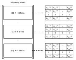
If there are in total P=R·C processors, then the adjacency matrix will be divided like below:
There are C columns and R·C block rows after this division. For each processor, they are in charge of C blocks, namely the processor (i,j) stores Ai,j(1) to Ai,j(C) blocks. The conventional 1D partitioning is equivalent to the 2D partitioning with R=1 or C=1.
In general, the parallel edge processing based on 2D partitioning can be organized in 2 communication phases, which are "expand" phase and "fold" phase.[6]
In the "expand" phase, if the edge list for a given vertex is the column of the adjacency matrix, then for each vertex v in the frontier, the owner of v is responsible to tell other processors in its processor column that v is visited. That's because each processor only stores partial edge lists of vertices. After this communication, each processor can traverse the column of according to the vertices and find out their neighbors to form the next frontier.[5]
In the "fold" phase, vertices in resulting next frontier are sent to their owner processors to form the new frontier locally. With 2D partitioning, these processors are in the same processor row.[5]
The main steps of BFS traversal in this 2D partitioning algorithm are(for each processor):
- expand phase (line 13–15): based on local vertices, only send messages to processors in processor-column to tell them these vertices are in the frontier, receive messages from these processors.
- (line 17–18): merge all receiving messages and form the net frontier N. Notice that not all vertices from received messages should be put into the next frontier, some of them may be visited already. The next frontier only contains vertices that has the distance value −1.
- fold phase (line 20–23): based on the local vertices in next frontier, send messages to owner processors of these vertices in processor-row.
- (line 25–28): merge all receiving messages and update the distance value of vertices in the next frontier.
The pseudo-code below describes more details of 2D BFS algorithm, which comes from the paper:[5]
1    define 2_D_distributed_memory_BFS( graph(V,E), source s):
2        // normal initialization
3        for all v in V do
4            d[v] = -1;
5        d[s] = 0;
6        // begin BFS traversal
7        for l = 0 to infinite do:
8            F = {the set of local vertices with level l}
9            // all vertices traversed
10           if F = {} for all processors then:
11               terminate the while loop
12           // traverse vertices by sending message to selected processor
13           for all processor q in this processor-column do:
14               Send F to processor q
15               Receive Fqr from q
16           // deal with the receiving information after the frontier traversal
17           Fr = Union{Fqr} for all q
18           N = {neighbors of vertices in Fr using edge lists on this processor}
19           // broadcast the neighbor vertices by sending message to their owner processor
20           for all processor q in this processor-row do:
21               Nq = {vertices in N owned by processor q}
22               Send Nq to processor q
23               Receive Nqr from q
24           // form the next frontier used for next layer traversal
25           Nr = Union{Nqr} for all q
26           // layer distance update
27           for v in Nr and d(v) = -1 do:
28               level = l + 1
In 2D partitioning, only columns or rows of processors participate in communication in "expand" or "fold" phase respectively.[5] This is the advantage of 2D partitioning over 1D partitioning, because all processors are involved in the all-to-all communication operation in 1D partitioning. Besides, 2D partitioning is also more flexible for better load balancing, which makes a more scalable and storage-efficient approach much easier.
Implementation optimization strategies
Aside from basic ideas of parallel BFS, some optimization strategies can be used to speed up parallel BFS algorithm and improve the efficiency. There are already several optimizations for parallel BFS, such as direction optimization, load balancing mechanism and improved data structure and so on.
Direction optimization
In original top-down BFS, each vertex should examine all neighbors of vertex in the frontier. This is sometimes not effective, when the graph has a low diameter.[7] but some vertices inside have much higher degrees than average, such as a small-world graph.[8] As mentioned before, one benign race in parallel BFS is that, if more than one vertex in the frontier has common neighbor vertices, the distance of neighbor vertices will be checked many times. Although the distance update is still correct with the help of synchronization, the resource is wasted. In fact, to find the vertices for the next frontier, each unvisited vertex only need to check if any its neighbor vertex is in the frontier. This is also the core idea for direction optimization. Even better is that, each vertex would quickly find a parent by checking its incoming edges if a significant number of its neighbors are in the frontier.
In the paper,[8] the authors introduce a bottom-up BFS where each vertex only needs to check whether any of their parents is in the frontier. This can be determined efficient if the frontier is represented by a bitmap. Compared to the top-down BFS, bottom-up BFS reduces the fail checking by self-examining the parent to prevent contention.
However, bottom-up BFS requires serializing work of one vertex and only works better when a large fraction of vertices are in the frontier. As a result, a direction optimized BFS should combine the top-down and the bottom-up BFS. More accurately, the BFS should start with the top-down direction, switch to the bottom-up BFS when the number of vertex exceeds a given threshold and vice versa.[8]
Load balance
Load balancing is very important not only in parallel BFS but also in all parallel algorithms, because balanced work can improve the benefit of parallelization. In fact, almost all of parallel BFS algorithm designers should observe and analyze the work partitioning of their algorithm and provide a load balancing mechanism for it.
Randomization is one of the useful and simple ways to achieve load balancing. For instance, in paper,[6] the graph is traversed by randomly shuffling all vertex identifiers prior to partitioning.
Data structure
thumb|alt=Four examples of pennant data structure based on k from 0 to 3.| Pennant data structure for k=0 to k=3.
There are some special data structures that parallel BFS can benefit from, such as CSR (Compressed Sparse Row), bag-structure, bitmap and so on.
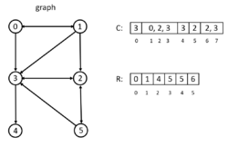
In the CSR, all adjacencies of a vertex is sorted and compactly stored in a contiguous chunk of memory, with adjacency of vertex i+1 next to the adjacency of i. In the example on the left, there are two arrays, C and R. Array C stores the adjacency lists of all nodes. Array R stored the index in C, the entry R[i] points to the beginning index of adjacency lists of vertex i in array C. The CSR is extremely fast because it costs only constant time to access vertex adjacency. But it is only space-efficient for 1D partitioning.[6] More information about CSR can be found in.[9] For 2D partitioning, DCSC (Doubly Compressed Sparse Columns) for hyper-sparse matrices is more suitable.[10]
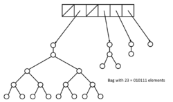
In the paper,[4] the authors develop a new data structure called bag-structure. Bag structure is constructed from the pennant data structure. A pennant is a tree of 2k nodex, where k is a nonnegative integer. Each root x in this tree contains two pointers x.left and x.right to its children. The root of the tree has only a left child, which is a complete binary tree of the remaining elements.[4]
The bag structure is the collection of pennants with a backbone array S. Each entry S[i] in S is either a null pointer or a pointer to a pennant with size si. The insertion operation in a bag takes O(1) amortized time and the union of two bags takes Θ(lgn) time. The bag-split takes also Θ(lgn) time. With this bag-structure, parallel BFS is allowed to write the vertices of a layer in a single data structure in parallel and later efficiently traverse them in parallel.[4]
Moreover, bitmap is also a very useful data structure to memorize which vertices are already visited, regardless in the bottom-up BFS.[11] or just to check if vertices are visited in the top-down BFS[9]
Benchmarks
Graph500 is the first benchmark for data-intensive supercomputing problems.[1] This benchmark generates an edge tuple with two endpoints at first. Then the kernel 1 will constructs an undirected graph, in which weight of edge will not be assigned if only kernel 2 runs afterwards. Users can choose to run BFS in kernel 2 and/or Single-Source-Shortest-Path in kernel 3 on the constructed graph. The result of those kernels will be verified and running time will be measured.
Graph500 also provides two reference implementations for kernel 2 and 3. In the referenced BFS, the exploration of vertices is simply sending messages to target processors to inform them of visited neighbors. There is no extra load balancing method. For the synchronization, AML (Active Messages Library, which is an SPMD communication library build on top of MPI3, intend to be used in fine grain applications like Graph500) barrier ensures the consistent traversal after each layer. The referenced BFS is only used for correctness verification of results. Thus, users should implement their own BFS algorithm based on their hardware. The choice of BFS is not constrained, as long as the output BFS tree is correct.
The correctness of result is based on the comparison with result from referenced BFS. Because only 64 search key are sampled to runs kernel 2 and/or kernel 3, the result is also considered correct when this result is different from referenced result only because the search key is not in samples. These 64 search keys also run the kernel sequentially to compute mean and variance, with which the performance of a single search is measured.
Different from TOP500, the performance metric in Graph500 is Traversed Edges Per Second(TEPS).
See also
References
- ↑ 1.0 1.1 Graph500
- ↑ "Designing multithreaded algorithms for breadth-first search and st-connectivity on the Cray MTA-2.", Bader, David A., and Kamesh Madduri. 2006 International Conference on Parallel Processing (ICPP'06). IEEE, 2006.
- ↑ 3.0 3.1 "Level-synchronous parallel breadth-first search algorithms for multicore and multiprocessor systems.", Rudolf, and Mathias Makulla. FC 14 (2014): 26-31.]
- ↑ 4.0 4.1 4.2 4.3 "A work-efficient parallel breadth-first search algorithm (or how to cope with the nondeterminism of reducers).", Leiserson, Charles E., and Tao B. Schardl. Proceedings of the twenty-second annual ACM symposium on Parallelism in algorithms and architectures. ACM, 2010.
- ↑ 5.0 5.1 5.2 5.3 5.4 "A scalable distributed parallel breadth-first search algorithm on BlueGene/L.", Yoo, Andy, et al. Proceedings of the 2005 ACM/IEEE conference on Supercomputing. IEEE Computer Society, 2005.
- ↑ 6.0 6.1 6.2 6.3 "Parallel breadth-first search on distributed memory systems.", Buluç, Aydin, and Kamesh Madduri. Proceedings of 2011 International Conference for High Performance Computing, Networking, Storage and Analysis. ACM, 2011.
- ↑ "Collective dynamics of ‘small-world’ networks.", Watts, Duncan J., and Steven H. Strogatz. nature 393.6684 (1998): 440.
- ↑ 8.0 8.1 8.2 "Direction-optimizing breadth-first search.", Beamer, Scott, Krste Asanović, and David Patterson. Scientific Programming 21.3-4 (2013): 137-148.
- ↑ 9.0 9.1 "Scalable GPU Graph Traversal", Merrill, Duane, Michael Garland, and Andrew Grimshaw. Acm Sigplan Notices. Vol. 47. No. 8. ACM, 2012.
- ↑ "On the representation and multiplication of hypersparse matrices." Buluc, Aydin, and John R. Gilbert. 2008 IEEE International Symposium on Parallel and Distributed Processing. IEEE, 2008.
- ↑ "Distributed-memory breadth-first search on massive graphs." Buluc, Aydin, et al. arXiv preprint arXiv:1705.04590 (2017).
 |

