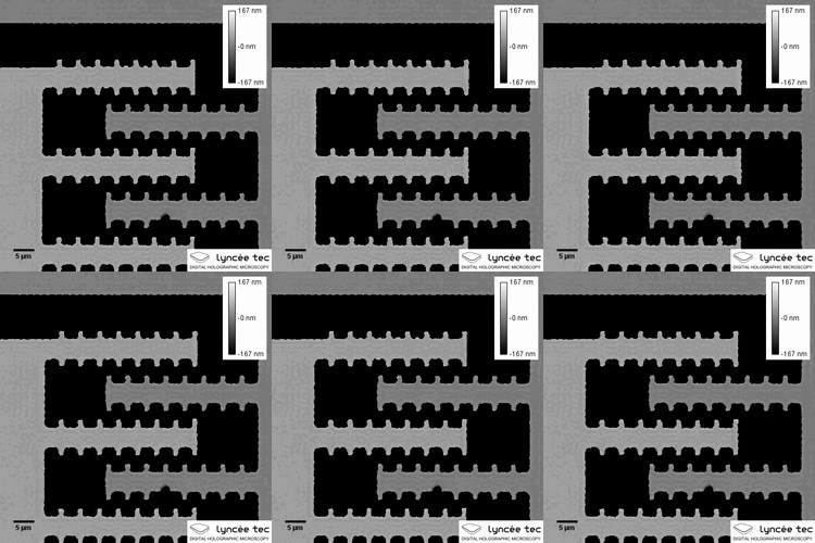
Engineering:Comb drive

Comb-drives are microelectromechanical actuators, often used as linear actuators, which utilize electrostatic forces that act between two electrically conductive combs. Comb drive actuators typically operate at the micro- or nanometer scale and are generally manufactured by bulk micromachining or surface micromachining a silicon wafer substrate.
The attractive electrostatic forces are created when a voltage is applied between the static and moving combs causing them to be drawn together. The force developed by the actuator is proportional to the change in capacitance between the two combs, increasing with driving voltage, the number of comb teeth, and the gap between the teeth. The combs are arranged so that they never touch (because then there would be no voltage difference). Typically the teeth are arranged so that they can slide past one another until each tooth occupies the slot in the opposite comb.
Restoring springs, levers, and crankshafts can be added if the motor's linear operation is to be converted to rotation or other motions.
The force can be derived by first starting with the energy stored in a capacitor and then differentiating in the direction of the force. The energy in a capacitor is given by:
[math]\displaystyle{ E = \frac{1}{2} C V^2 }[/math]
[math]\displaystyle{ F = \frac{1}{2} \frac{\partial C}{\partial dx_{drive}} V^2 }[/math]
Using the capacitance for a parallel plate capacitor, the force is:
[math]\displaystyle{ F = \frac{-1}{2}\frac{nt\epsilon_o\epsilon_rV^2}{d} }[/math]
[math]\displaystyle{ V }[/math] = applied electric potential,
[math]\displaystyle{ \epsilon_r }[/math] = relative permittivity of dielectric,
[math]\displaystyle{ \epsilon_o }[/math] = permittivity of free space (8.85 pF/m),
[math]\displaystyle{ n }[/math] = total number of fingers on both sides of electrodes,
[math]\displaystyle{ t }[/math] = thickness in the out-of-plane direction of the electrodes,
[math]\displaystyle{ d }[/math] = gap between electrodes.
Structure of Comb-drives
• rows of interlocking teeth • half fixed • half part of movable assembly • electrically isolated • electrostatic attraction/repulsion – CMOS drive voltage • many teeth increased force – typically 10μm long and strong
Scaling Issues
Comb drives cannot scale to large gap distances (equivalently actuation distance), since development of effective forces at large gaps distances would require high voltages—therefore limited by electrical breakdown. More importantly, limitations imposed by gap distance limits the actuation distance.
See also
References
- ↑ Tsoukalas, Konstantinos; Vosoughi Lahijani, Babak; Stobbe, Søren (2020-06-05). "Impact of Transduction Scaling Laws on Nanoelectromechanical Systems". Physical Review Letters 124 (22): 223902. doi:10.1103/PhysRevLett.124.223902. PMID 32567909. Bibcode: 2020PhRvL.124v3902T. https://link.aps.org/doi/10.1103/PhysRevLett.124.223902.
- Legtenberg, Rob; Growenveld, AW; Elwenspoek, M (1996). "Comb Drive Actuators for Large Displacements". J. Micromech. Microeng. 6 (3): 320–9. doi:10.1088/0960-1317/6/3/004. Bibcode: 1996JMiMi...6..320L. https://research.utwente.nl/en/publications/combdrive-actuators-for-large-displacements(ac0e6e69-1224-4404-94eb-564fcd1ba8b2).html.
 |


