Engineering:Deflection yoke
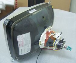
A deflection yoke is a kind of magnetic lens, used in cathode ray tubes to scan the electron beam both vertically and horizontally over the whole screen.
In a CRT television, the electron beam is moved in a raster scan on the screen. By adjusting the strength of the beam current, the brightness of the light produced by the phosphor on the screen can be varied. The cathode ray tube allowed the development of all-electronic television.
Electromagnetic deflection yokes are also used in certain radar displays.[1]
Magnetic compared to electrostatic deflection
Another way of deflecting an electron beam is to put two pairs of electrodes inside the CRT, after the electron gun structure. Electrostatic deflection is common in oscilloscope displays, because it is easier to drive deflection plates at high frequencies, compared to driving the large inductance of a deflection yoke. Compared with electrostatic deflection, magnetic deflection has fewer obstructions inside the tube and so allows for a larger-diameter electron beam, producing a brighter image. This is an advantage for a raster-scan display, which must cover the whole screen instead of one narrow trace as in an oscilloscope.
Additionally, magnetic deflection can be arranged to give a larger angle of deflection than electrostatic plates; this makes the CRT and resulting television receiver more compact. The angle of magnetic deflection, for a given deflection current, is inversely proportional to the square root of the CRT accelerating voltage, but in electrostatic deflection, the angle is inversely proportional to the accelerating voltage (for a particular value of deflection plate voltage). This has the practical effect that high accelerating voltages can be used without greatly increasing the power of the deflection amplifiers.[1]
While a magnetic deflection yoke can be used to provide a random-access vector display image, the high inductance of the yoke windings requires powerful amplifiers that may be expensive to produce with high bandwidth. In a raster scan display used for television or computer displays, the energy stored in the deflection system is recovered and used to develop the high voltage (10,000 volts or more) used to generate the electron beam in the CRT.
Structure
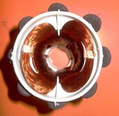
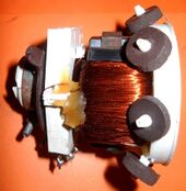
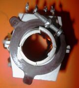
The deflection yoke has two sets of coils, perpendicular to each other and to the neck of the cathode ray tube. The coils are bent into a rough saddle-shape, to conform to the neck of the CRT and to provide a linear magnetic field distribution. In a color television receiver, three electron beams are all scanned in unison by the single deflection yoke. In a television receiver, the deflection coil may include ferrite segments to help direct and concentrate the magnetic field.
See also
- Quadrupole magnet
- Magnetic deflection
- Electron beam processing
- Analog television
- Analog television § Displaying an image
- Nipkow disk
- Image dissector
- Scan line
References
 |


