Engineering:Western Electric hand telephone sets
The Western Electric hand telephone sets comprise a series of telephones that were produced from 1927 by the Western Electric Company for the American Telephone and Telegraph Company (AT&T) and the Bell System. The series features the mouthpiece (transmitter) and the earpiece (receiver) combined into a hand-held unit, originally named a hand telephone, or handset. The handset would be held against the ear and in front of the mouth simultaneously, in contrast to earlier telephones in the Bell System where only the receiver was held against the ear, while the user spoke into a fixed transmitter mounted on a telephone stand or wall telephone.
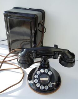
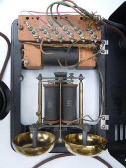
Hand telephone sets consist of three principal parts: the handset, a handset mounting, and an apparatus box, called variously desk set box, bell box, subscriber set, or just subset. This box is typically mounted on a wall or desk-side, and contains an electromagnetic bell ringer and a speech transformer, called induction coil, to connect the telephone to the telephone line wiring. The handset mounting is either a desk-top stand to cradle and secure the handset when not in use, or a small box mounted against a vertical surface or wall that featured a switch-hook for hanging the handset.
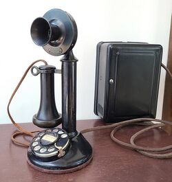
Other American and foreign telephone manufacturers had already produced this type of telephone, often referred to as French phone. In the Bell System, hand telephones formally replaced the hitherto used deskstand, colloquially called candlestick, by the end of the 1920s, although reconditioned candlestick telephones remained in service for at least another two decades.
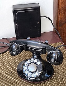
The shape and styling of these telephones by Western Electric evolved from the candlestick. Three main styles resulted for use on the desk-top, designated the type A, type B, and type D handset mounting. A and B had a circular base, while type D is identified by its elliptical footprint. The most notable examples of telephones constructed from the handset mountings, are the model 102 and the model 202 telephones, variants which differed in their electric circuitry, with improvements of speech performance. In addition, the type C, and later type G, handset mountings were small wall-mounted units for hanging up the handset.
The 1927 handset and its telephone stand marked a milestone in AT&T's telephone development and of the Bell System, as it represented a new design methodology, away from inspired invention and empirical testing and toward theoretical planning and quantitative testing and quality assurance. It became the origin of all later telephone instruments in the Bell System.[1]
History
Hand telephones
The concept of a hand-held one-piece device that a telephone user would hold against ear and in front of the mouth arose in London shortly after the official invention of the telephone. Although early patents by C. E. McEvoy and G. E. Pritchett did not yield commercial devices in 1877,[2] R. G. Brown of New York succeeded the following year in devising a combined transmitter and receiver handset, that he used in a local telephone exchange system in the district of the New York Gold and Stock Exchange.[3] Having little success in promoting the device elsewhere in the U.S., Brown left for France to become Electrical Engineer of La Société Générale des Telephones in Paris. There, his designs found resonance and adaptations became widely used in Europe, where they became known as French phones.[3][4]
In the following decade, Western Electric experimented with three handset types, which were produced in limited quantities.[3] Derivatives were used in the early 1900s for use as linemen telephone sets, but none were found adequate for use in the Bell System. While already popular in other countries, Western Electric produced handsets for export into the European market,[5] but the Bell System had more stringent requirements than any other administration, due to the long distances of communication involved.[6]
Technical obstacles
Two major technical problems prevented the handset from reaching production stage for use by subscribers in the Bell System. Firstly, the transmitters of the day did not work well unless oriented steadily in a vertical plane. A handset would be used in many positions and orientations. If operated at other angles, carbon granules in the transmitter would shift and move in an unacceptable manner, resulting in poor voice quality.[7] The second hurdle to the acceptance of a common handset model was that audio from the receiver was picked up acoustically by the transmitter and amplified.[5] This resulted in howling tones, due to the hollow handles providing an acoustic channel between receiver and transmitter. The problems were aggravated by the signal boosting circuitry used in the subscriber set which resulted in a strong signal (sidetone) at the receiver of the speech of the user.[8] Sidetone is the reproduction of sound through a local path from the transmitter to the receiver in the telephone.[9] It is desirable only to some fraction of volume so that the user has the assurance that the telephone is working correctly. Strong sidetone may cause users to lower the voice to unacceptable levels, so that the recipient receives insufficient signal level.

Circuit theory and handset solutions
During the 1910s, the reasons for these problems became well understood, but remedies remained elusive. After the end of World War I, new efforts concentrated on the resolution of these deficiencies, as new research yielded insight into electric circuit theory for anti-sidetone compensation, and new hope of progress.[11][5] In the 1920s, developments of non-positional transmitters, which worked in any orientation, permitted Western Electric to develop a handset model essentially free of these problems. The construction of the handset was changed from using hollow metal handles to solid Bakelite, a molded plastic material that was gaining acceptance in the telephone industry. With the solid construction the engineers were able to suppress acoustic feedback from receiver to transmitter to acceptable levels, by elevating the mechanical resonance frequencies of the handset sufficiently to avoid interference with the speech range. The resulting device was ready for distribution around the start of 1927.[12]
Alongside the development of the handset, engineers at Bell Telephone Laboratories also worked on improvements of telephone circuitry that assisted in the quality of speech conversion and transmission. While already used in telephone operator circuitry, this anti-sidetone circuit was not ready for the first hand telephones,[13] but had to wait for the early 1930s.
Handset mountings
The completed handset was paired with a stand that had been in used for several years in the development stages of the handset. It was essentially a candlestick base with a shortened shaft of approximately one and one half inch in height, topped with a new cradle for the handset. It was later referred to as the type A handset mounting.
The release of the new hand telephone set uncovered mechanical flaws, so that a new base was designed to replace the shortened candlestick. The result was the type B handset mounting introduced later in 1927. It still retained a circular footprint of the base, but improved on the esthetic appearance. The B-type desk set was followed by a wall-mounted hand telephone set, designated as the type C handset mounting, also referred to as a hangup telephone, with the handset hanging on one side of the unit in a switchhook fork that cradled only the receiver cup.
In use, the B-type telephone base proved unstable during dialing, and was replaced with the type D handset mounting by 1930. A wider, elliptical footprint improved its stability. The D handset mounting was initially deployed with the same electric circuit (booster circuit) as the prior models. This new style of telephone also prompted a modernization in style of the subscriber sets, yielding updated, smaller, and less costly units.
Anti-sidetone circuit
While the construction of the handset with a solid Bakelite handle had eliminated the howling by mechanical (acoustic) feedback from the receiver to the transmitter, it did not reduce the electrical feedback from the transmitter to the receiver due to the coupling of these elements through the induction coil, which was particularly annoying in a noisy room, because the background noise could overwhelm the speech signal received from the distant party, and when speaking, users would hear themselves very loudly too. This was improved with the anti-sidetone speech circuitry which was finally introduced the following year (1931) in new sections for equipment in the Bell System Practices. However, with the onset of the worst years of the Great Depression, distribution of telephone sets with this new circuit was largely delayed. New and existing telephone service installations in the U.S. were in decline and staffing at Western Electric was reduced by eighty percent.[14][15]
The anti-side tone circuit featured a three-winding induction coil, rather than a simple two-winding transformer. The third winding compensates a part of the sidetone by superimposing a phase-inverted portion of the transmitter signal.[9][16] This reduced the loudness of the user's own speech in the receiver, but left enough to avoid complete silence in the ear of the user, which might be interpreted as a device failure.
Telephone assembly codes
With the completion of the anti-sidetone circuit, in 1930 Western Electric began assigning assembly codes to telephones based on the type of electrical configuration.[17] Until then, the hand telephone sets were primarily referred to by the handset mountings used to construct them. With the new circuit variant, this became insufficient, resulting in the distinction between 100-series and 200-series hand telephone sets. Thus, the type 102 was the new designation for a handset mounting when used on common battery lines with a side-tone circuit,[18] and the 202 was the anti-sidetone version.[19] Initially, this referred to B-type handset mountings, but by the time the 200-series anti-sidetone hand telephone sets were documented in the Practices, the standard base was the D handset mounting. At that time, the 100-series assembly codes were also redefined by use of the D handset mounting,[20] so that the assembly code 102 was no longer used for A- or B-type handset mountings.[21] However, they were covered by the same specifications and maintenance procedures.[21][22]
Type A handset mounting
The first version of the new hand telephone sets was marked by AT&T as D-76869, a specification type for small quantities of new equipment. The device was described by George K. Thompson of the American Telephone and Telegraph Company (AT&T) in United States patent No. 1508424 of 1924, without showing the handset that was still in development.[10] During 1927, it became known and labeled as the type A handset mounting, embodied in the A1, A2, and A3 telephones.
This type was directly derived from the candlestick telephone. The vertical tube shaft of the deskstand was shortening in height to about one and one half inches. Mounted on top of this was placed a cradle device that held the combined handset in a horizontal position. It incorporated a switch bar that would be depressed when the handset was in place. A vertical plunger operates an internal switch when the handset is lifted to connect the telephone to its subset and the telephone line. Telephones built with this handset mounting were released in limited supply in 1927, and were known as the A1 telephone, the most common type for local and common battery service. The A2 handset mounting was made for special measured two-party line service and the A3 was for private telephone and residence systems.[23]
Type B handset mounting
By the end of 1927, well within a year of introduction of the A1 telephone, William H. Scharringhausen of the Bell Telephone Laboratories streamlined the design and filed a patent application on November 29, 1927.[24] He integrated the short tubular neck into the continuous contours of the base. The circular footprint of the base was retained. The design corrected mechanical failures in the A handset mounting to position the handset properly when placed onto the desk set.[25] The new design became known as the type B handset mounting.[23] The most common variety, was the B1A hand telephone set, which was used for local battery telephones with a wooden subscriber set and magneto box, and for common battery lines with a steel-enclosure subscriber set (No. 534A). In 1930, the designation was superseded by 102 type hand telephone set. Manual (no dial) instruments were indicated by the letter suffix A (i.e. 102A) and dial instruments received the suffix B, C, or D, depending on the style of digit and letter display on the dial.[18]
The B-type hand telephone sets were typically installed with a black finish (suffix -3), but sets in ivory, gray, old brass, statuary bronze, and oxidized silver tones could be ordered by customers. Color was indicated by numeric suffices to the assembly code.
Type D handset mounting
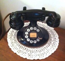
In 1929, the Bell System sought to improve the appearance of their telephone apparatus, particularly in subscriber's homes and offices. After a design contest failed to produce useable ideas,[26] by year-end engineers had redesigned the desk-top handset mounting into a new, wider, elliptical shape that also recessed the casing of the dial, which was previously simply mounted on top of the front slope of the base.[27][28] While using the same handset, the telephone's overall dimensions now conformed to the Golden Section.[29]
This design was referred to as the type D handset mounting. Service-specific telephone models were again designated by numerical suffices (D1, D2, etc.). In 1930, it formally replaced the B handset mounting in 102-type telephones, and in 1931 it became the standard base for the 202. However, type B handset mountings continued to be produced until c. 1932, and installation of 202-type telephones with the anti-sidetone circuit were delayed due to the economic conditions of the Great Depression.
Telephones based on the D handset mounting were made available in more colors than the previous types. In 1930, consultants to the Bell Laboratories suggested changes and additional colors to the previous palette: ivory, gray-green, old rose, Pekin red, and dark blue were now in fashion, in addition to the metallic hues called old brass, dark gold, statuary bronze, and oxidized silver.[30]
Along with the new look of the telephone, the effort complemented it with a new subscriber set in 1930, the type 584.[31][32] It formally replaced the larger, but electrically equivalent type 534, which had featured a large steel housing. The new subscriber set was about half the size, was lighter, cheaper to manufacture, and had a cover molded from Bakelite, a material that was becoming fashionable in the era of Art Deco design. For colored telephone sets, the subscriber set was painted in the same color.
102 hand telephone set
The type 102 hand telephone set is a desk-top handset mounting with the traditional electric circuit, so called booster circuit, that used a two-winding induction coil, i.e. a simple transformer, without sidetone compensation.[17] When the designation was created in 1930 the then current handset mounting for this telephone was the B1 handset mounting. The D1 handset mounting was substituted for this assembly code shortly after, when it was released to the operating companies, and documented in the Bell System Practices. For field work, where the assembly code was not important,[33] the procedures for the 102 specification were extended to the prior A and B handset mountings.[22]
The 102 desk set was connected to the subscriber set with a three-conductor mounting cord.[22]
202 hand telephone set
When designating anti-sidetone apparatus, the Bell System practice was to add the value 100 to the apparatus code of the corresponding sidetone equipment.[34] Thus, the new hand telephone set with the anti-side tone circuit was the type 202 hand telephone set.[17]
The anti-sidetone circuit required an additional, fourth conductor in the mounting cord to the subscriber set. For this telephone Western Electric produced a new type of subscriber sets, the No. 684A, which featured the same more compact form factor of the type No. 584, previously. When the 202 was introduced in mid-1931,[19] the U.S. economy was still in deep recession, and installations of new equipment was generally delayed until conditions improved.
When the Bell System introduced the Type 302 combined telephone set in 1937, with a newly styled handset, the hand telephone sets, including the 202 were manufactured or refurbished with this new handset of type F1. The F1 contained more efficient transmitter and receiver elements.
Later-evolving versions
thumb|A Western Electric 202 Imperial telephone as issued in 1955 with a gold lacquered base and ivory Tenite plastic handset. The subscriber set (rear) was painted in harmonizing color to the desk set. In 1937, Bell Telephone Laboratories and Western Electric began shipping a new telephone design, the model 302 telephone, to the Associated Companies of the Bell System, a combined telephone set that combined all components into one housing, eliminating the separate bell box. It also featured a new type of handset (F1) with improved transmitter and receiver elements. With this development, the manufacture of the D-handset mountings and the 202 hand telephone sets was ended in 1939.
The new handset became the new standard in the Bell System and was used in refurbishing existing hand telephone sets for reissue as 202-type sets for almost another two decades.
In the 1950s, large quantities of old telephones were retired in favor of the popular new model 500 telephone, creating a stock pile of still usable parts. At the same time, popular demand provided pressure in the market place to produce colored telephones. The manufacturing processes to produce this new line of 500-type sets in color were not completed yet and those sets were only issued in black until 1954. In 1955, Western Electric reissued the 202 telephone painted in several colors. The Continental line was created from a D1 base with an F1 handset, and was available painted in primarily ivory, green, red, and black,[35] but other colors were made available by special customer order. The Silver Continental was plated in silvery rhodium, and the Imperial was sprayed with gold lacquer. Both were issued with an ivory painted Bakelite or ivory thermoplastic handset of the type F1.
In the 1960s, AT&T introduced a very different design, a departure from the traditional hand telephone set, the Trimline telephone. Formally, it was referred to by its apparatus code, the No. 220 hand telephone set. It comprised a molded dial-in-handset,[36] that was a complete telephone except for the ringer and switch hook functions, which were provided in a plastic base unit that served to cradle the handset when not in use.
Wall-mounted hand telephones
In 1928, Western Electric introduced the Type C handset mounting for the newly developed combined handset. It was mounted against the side of a desk, or on a wall, without requiring desk top space, and had a sideways-oriented cradle for hanging the handset. With the introduction of assembly codes in 1930, telephone sets were coded as the 101 and 201 hand telephone sets, with a sidetone and anti-sidetone circuit, respectively. In 1936, the hangup-type hand telephone set was redesigned as the type G handset mounting to produce the 211 anti-sidetone telephone, as well as a series of other types (212, 213, 214) for special service modifications. This type of telephone set was produced well into the 1970s, and is often colloquially referred to as a space-saver telephone.
See also
References
- ↑ Bell Telephone Laboratories, Staff, M.D. Fagan (Ed.), A History of Engineering and Science in the Bell System–The Early Years (1875–1925), 1975, p.153
- ↑ Frederick H.A., Bell Laboratories Record 12(11) 322 (July 1934), Early Handsets, p.323
- ↑ 3.0 3.1 3.2 Bell Telephone Laboratories, Staff, M.D. Fagan (Ed.), A History of Engineering and Science in the Bell System–The Early Years (1875–1925), 1975, p.140
- ↑ Brooks, John (1975). Telephone–The First Hundred Years. Harper & Row. p. 129. ISBN 0-06-010540-2.
- ↑ 5.0 5.1 5.2 BTL, Early Years, p. 144
- ↑ BTL, Early Years, p. 142
- ↑ Mountjoy, Richard (1995). 100 Years of Bell Telephones. Schiffer Publishing. pp. 138. ISBN 0-88740-872-9.
- ↑ Meyer, Ralph O. (2005). Old Time Telephones! Design, History, and Restoration. Schiffer Publishing. pp. 63. ISBN 0-7643-2282-6.
- ↑ 9.0 9.1 AT&T, Bell System Practices, Section C30.001 Issue 1 (March 16, 1932) Common Battery Anti-Sidetone Stations
- ↑ 10.0 10.1 US patent 1508424, G. K. Thompson, "Telephone Desk Set", issued 1924-09-16
- ↑ US patent 1402322, George K. Thompson, "Anti-Side-Tone Hand Set", issued 1922-01-03
- ↑ Brooks, John (1975). Telephone–The First Hundred Years. Harper & Row. p. 179. ISBN 0-06-010540-2.
- ↑ Meyer, Ralph O. (2005). Old Time Telephones! Design, History, and Restoration. Schiffer Publishing. pp. 64. ISBN 0-7643-2282-6.
- ↑ Page, Arthur W. (1941). The Bell Telephone System. New York: Harper & Brothers Publishers. p. 212.
- ↑ Brooks, John (1975). Telephone–The First Hundred Years. Harper & Row. p. 188. ISBN 0-06-010540-2.
- ↑ J. W. Foley, Bell Laboratories Record 17(11) 347 (July 1939) The Anti-Sidetone Station Circuit
- ↑ 17.0 17.1 17.2 AT&T, Bell System Practices, Section C32.111 Issue 2 (December 1, 1937) Hand Telephone Sets, Desk Types–Description
- ↑ 18.0 18.1 AT&T, Bell System Practices Section C32.101 Issue 1 (1 August 1930), Hand Telephone Sets—B Types—Description and Use
- ↑ 19.0 19.1 AT&T, Bell System Practices, Section C32.103 Issue 1 (1 June 1931) Anti-Sidetone Hand Telephone Sets–201, 202, 203, 205, 206, and 207 Types–Description and Use
- ↑ AT&T, Bell System Practices, Section C32.102 Issue 2 (1 June 1931) Sidetone Hand Telephone Sets–101, 102, 103, 104, and 105 Types–Description and Use
- ↑ 21.0 21.1 AT&T, Bell System Practices, Section C44.101 Issue 2 (1 November 1931, Sidetone Hand Telephone Sets–101, 102, 103, 104, and 105 Types–Connections, p.1
- ↑ 22.0 22.1 22.2 AT&T, Bell System Practices, Section C32.160 Issue 1 (1 November 1931) Sidetone Hand Telephone Sets–101, 102, 103, 104, and 105 Types–Cording
- ↑ 23.0 23.1 AT&T, Handbook Specification 4810 (December 1927), Stations–Hand Telephone Sets
- ↑ US patent 1788747, W. H. Scharringhausen, "Telephone Desk Set", issued 1931-01-13
- ↑ W. H. Scharringhausen (November 1927) Telephone Desk Set, US Patent 1,788,747 (January 13, 1031)
- ↑ Hadlaw, J. The design contest : the function, form, and meaning of the Bell telephone,1920-1939, in Objects & Communication, Media and Information (MEI) 30-31 (23) 329 (April 2010) p.337
- ↑ B. Gherardi, F.B. Jewett, Bell System Technical Journal 9(1)1 (January 1930), Telephone Communication System of the United States, p.10
- ↑ Kempster Miller, Telephone Theory and Practice, Vol 2 (1933) p.106.
- ↑ Dilts M.M. The Golden Section, Bell Laboratories Record 10(3) 97 (November 1931)
- ↑ G. A. Wahl, Bell Laboratories Record 34(8) 252 (July 1956) Telephone Sets in Color, p.252
- ↑ Lohmeyer, Frank, Bell Laboratories Record 10 (2) 43 (October 1931), A Small Subscriber Set
- ↑ AT&T, Handbook specification No. 4588–Supplement A (June 1930) Dial and Manual CB Stations–584 Type Subscriber Set
- ↑ AT&T, Bell System Practices, Section C32.301 Issue 2 (June 1, 1931) Hand Set Mountings–A to E Types–Description
- ↑ AT&T, Bell System Practices, Section C30.001 Issue 1 (March 16, 1932) Common Battery Anti-Sidetone Stations, p.2 paragraph 3.02
- ↑ AT&T, Bell System Practices, Section C32.111 Addendum Issue 2 (March 1955) Hand Telephone Sets–Desk Type–Description, p.1
- ↑ W.E. Whidden, An Experimental "Dial-In-Handset"Telephone, Bell Laboratories Record 38(1)23 (January 1960)
 |
