Engineering:Gimbaled thrust
Gimbaled thrust is the system of thrust vectoring used in most rockets, including the Space Shuttle, the Saturn V lunar rockets, and the Falcon 9.
Operation
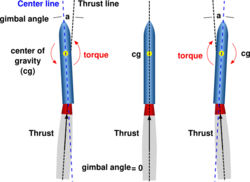
In a gimbaled thrust system, the engine or just the exhaust nozzle of the rocket can be swiveled on two axes (pitch and yaw) from side to side. As the nozzle is moved, the direction of the thrust is changed relative to the center of gravity of the rocket.
The diagram illustrates three cases. The middle rocket shows the straight-line flight configuration in which the direction of thrust is along the center line of the rocket and through the center of gravity of the rocket. On the rocket at the left, the nozzle has been deflected to the left and the thrust line is now inclined to the rocket center line at an angle called the gimbal angle. Since the thrust no longer passes through the center of gravity, a torque is generated about the center of gravity and the nose of the rocket turns to the left. If the nozzle is gimbaled back along the center line, the rocket will move to the left. On the rocket at the right, the nozzle has been deflected to the right and the nose is moved to the right.
Details and examples
Thrust vectoring for many liquid rockets is achieved by gimbaling the whole engine. This involves moving the entire combustion chamber and outer engine bell as on the Titan II's twin first-stage motors, or even the entire engine assembly including the related fuel and oxidizer pumps. The Saturn V and the Space Shuttle used gimbaled engines.[1]
A later method developed for solid propellant ballistic missiles achieves thrust vectoring by deflecting only the nozzle of the rocket using electric actuators or hydraulic cylinders. The nozzle is attached to the missile via a ball joint with a hole in the centre, or a flexible seal made of a thermally resistant material, the latter generally requiring more torque and a higher power actuation system. The Trident C4 and D5 systems are controlled via hydraulically actuated nozzle. The STS SRBs used gimbaled nozzles.[2]
References
- ↑ George P. Sutton, Oscar Biblarz, Rocket Propulsion Elements, 7th Edition.
- ↑ Reusable Solid Rocket Motor—Accomplishments, Lessons, and a Culture of Success. 27 September 2011. https://ntrs.nasa.gov/archive/nasa/casi.ntrs.nasa.gov/20120001536.pdf. Retrieved February 26, 2015.
- NASA. "Gimbaled Thrust". Beginner's Guide to Rockets. https://www.grc.nasa.gov/www/k-12/rocket/gimbaled.html. Retrieved 2006-01-07. Public domain source.
 |


