Engineering:HB9XBG Antenna
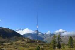
The HB9XBG antenna is a vertical dipole antenna for short wave radio amateurs. It was developed by the Swiss radio amateur Walter Kägi, whose call sign HB9XBG is also the designation of the antenna.[1] During the test phase in 2020, HB9XBG built two vertical dipoles – one for the 20-metre amateur radio band and another for the 40-metre band. The antennas were tested on Simplon Pass at an altitude of 2,040 metres. The structure of the HB9XBG antenna was first published in 2020 in HBradio, the journal of the Union of Swiss Short Wave Amateurs.[2][3]
Principle of the antenna
Vertical half-wave dipoles such as sleeve or coaxial antennas make simultaneous use of the lower half of the dipole as a feedline and a radiator. These antennas do not need a ground grid or radials; they require little space and their feed systems are relatively simple. The radiation resistance at dipole centre of a vertical dipole depends on the height of the installation. If the end of the lower dipole leg is λ/80 above ground, i.e. close to the ground, the radiation resistance is 100 Ω.[4] The conductivity and dielectric characteristics of the ground exert little influence on the radiation resistance.
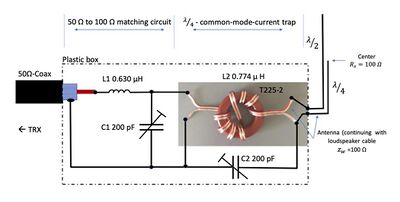
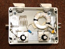
The HB9XBG antenna is based on the use of a speaker audio cable with a strand cross-section of 2 × 2.5 mm2 and PVC insulation. A speaker cable of this kind has an impedance of almost exactly 100 Ω and performs two functions at the same time: the function of the feedline as far as the centre of the dipole and the function of the "radiating common mode current" for the lower dipole leg. One core of the two-core cable is removed on the upper half of the dipole. A resonant trap L2/C2 eliminates the common mode current at the lower end of the antenna.[2] The L1/C1 components (see the illustration) matches the feedline impedance of 50 Ω to the 100 Ω system of the antenna.
Despite the fact that the feedpoint for the antenna is applied at the base, electrically it is a centre fed dipole.
Advantages of the HB9XBG antenna
Source:[2]
• Low-impedance feed (100 Ω)
• High bandwidth, flat SWR curve (900 kHz, SWR less than 1.5)
• No antenna tuner required
• High level of efficiency (virtually no SWR losses)
• Installation only a few centimetres above ground (ground-neutral)
• Functions well over rocky terrain and ideal for Summits on the Air
• No radials/counterpoises required
• Low take off angle of radiation, ideal for DX
• 6 dBi antenna gain over ideal terrain
• Requires little space
• Rapid setup and dismantling
• Suitable for portable operation
• Ideal for self-construction
References
 |


