Physics:Electrostatic generator
An electrostatic generator, or electrostatic machine, is an electrical generator that produces static electricity, or electricity at high voltage and low continuous current. The knowledge of static electricity dates back to the earliest civilizations, but for millennia it remained merely an interesting and mystifying phenomenon, without a theory to explain its behavior and often confused with magnetism. By the end of the 17th century, researchers had developed practical means of generating electricity by friction, but the development of electrostatic machines did not begin in earnest until the 18th century, when they became fundamental instruments in the studies about the new science of electricity.
Electrostatic generators operate by using manual (or other) power to transform mechanical work into electric energy, or using electric currents. Manual electrostatic generators develop electrostatic charges of opposite signs rendered to two conductors, using only electric forces, and work by using moving plates, drums, or belts to carry electric charge to a high potential electrode.
Description
Electrostatic machines are typically used in science classrooms to safely demonstrate electrical forces and high voltage phenomena. The elevated potential differences achieved have been also used for a variety of practical applications, such as operating X-ray tubes, particle accelerators, spectroscopy, medical applications, sterilization of food, and nuclear physics experiments. Electrostatic generators such as the Van de Graaff generator, and variations as the Pelletron, also find use in physics research.
Electrostatic generators can be divided into categories depending on how the charge is generated:
- Friction machines use the triboelectric effect (electricity generated by contact or friction)
- Influence machines use electrostatic induction
- Others
Friction machines
History
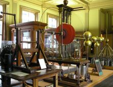
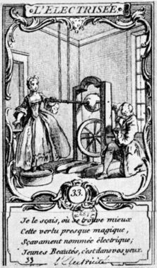
The first electrostatic generators are called friction machines because of the friction in the generation process. A primitive form of frictional machine was invented around 1663 by Otto von Guericke, using a sulphur globe that could be rotated and rubbed by hand. It may not actually have been rotated during use and was not intended to produce electricity (rather cosmic virtues),[1] but inspired many later machines that used rotating globes. Isaac Newton suggested the use of a glass globe instead of a sulphur one.[2] About 1706 Francis Hauksbee improved the basic design,[3] with his frictional electrical machine that enabled a glass sphere to be rotated rapidly against a woollen cloth.[4]
Generators were further advanced when, about 1730, Prof. Georg Matthias Bose of Wittenberg added a collecting conductor (an insulated tube or cylinder supported on silk strings). Bose was the first to employ the "prime conductor" in such machines, this consisting of an iron rod held in the hand of a person whose body was insulated by standing on a block of resin.
In 1746, William Watson's machine had a large wheel turning several glass globes, with a sword and a gun barrel suspended from silk cords for its prime conductors. Johann Heinrich Winckler, professor of physics at Leipzig, substituted a leather cushion for the hand. During 1746, Jan Ingenhousz invented electric machines made of plate glass.[5] Experiments with the electric machine were largely aided by the discovery of the Leyden Jar. This early form of the capacitor, with conductive coatings on either side of the glass, can accumulate a charge of electricity when connected with a source of electromotive force.
The electric machine was soon further improved by Andrew (Andreas) Gordon, a Scotsman and professor at Erfurt, who substituted a glass cylinder in place of a glass globe; and by Giessing of Leipzig who added a "rubber" consisting of a cushion of woollen material. The collector, consisting of a series of metal points, was added to the machine by Benjamin Wilson about 1746, and in 1762, John Canton of England (also the inventor of the first pith-ball electroscope) improved the efficiency of electric machines by sprinkling an amalgam of tin over the surface of the rubber.[6] In 1768, Jesse Ramsden constructed a widely used version of a plate electrical generator.[clarification needed]
In 1783, Dutch scientist Martin van Marum of Haarlem designed a large electrostatic machine of high quality with glass disks 1.65 meters in diameter for his experiments. Capable of producing voltage with either polarity, it was built under his supervision by John Cuthbertson of Amsterdam the following year. The generator is currently on display at the Teylers Museum in Haarlem.
In 1785, N. Rouland constructed a silk-belted machine that rubbed two grounded tubes covered with hare fur. Edward Nairne developed an electrostatic generator for medical purposes in 1787 that had the ability to generate either positive or negative electricity, the first of these being collected from the prime conductor carrying the collecting points and the second from another prime conductor carrying the friction pad. The Winter machine[clarification needed] possessed higher efficiency than earlier friction machines.
In the 1830s, Georg Ohm possessed a machine similar to the Van Marum machine for his research (which is now at the Deutsches Museum, Munich, Germany). In 1840, the Woodward machine was developed by improving the 1768 Ramsden machine, placing the prime conductor above the disk(s). Also in 1840, the Armstrong hydroelectric machine was developed, using steam as a charge carrier.
Friction operation
The presence of surface charge imbalance means that the objects will exhibit attractive or repulsive forces. This surface charge imbalance, which leads to static electricity, can be generated by touching two differing surfaces together and then separating them due to the phenomenon of the triboelectric effect. Rubbing two non-conductive objects can generate a great amount of static electricity. This is not the result of friction; two non-conductive surfaces can become charged by just being placed one on top of the other. Since most surfaces have a rough texture, it takes longer to achieve charging through contact than through rubbing. Rubbing objects together increases amount of adhesive contact between the two surfaces. Usually insulators, e.g., substances that do not conduct electricity, are good at both generating, and holding, a surface charge. Some examples of these substances are rubber, plastic, glass, and pith. Conductive objects in contact generate charge imbalance too, but retain the charges only if insulated. The charge that is transferred during contact electrification is stored on the surface of each object. Note that the presence of electric current does not detract from the electrostatic forces nor from the sparking, from the corona discharge, or other phenomena. Both phenomena can exist simultaneously in the same system.
Influence machines
History
Frictional machines were, in time, gradually superseded by the second class of instrument mentioned above, namely, influence machines. These operate by electrostatic induction and convert mechanical work into electrostatic energy by the aid of a small initial charge which is continually being replenished and reinforced. The first suggestion of an influence machine appears to have grown out of the invention of Volta's electrophorus. The electrophorus is a single-plate capacitor used to produce imbalances of electric charge via the process of electrostatic induction.
The next step was when Abraham Bennet, the inventor of the gold leaf electroscope, described a "doubler of electricity" (Phil. Trans., 1787), as a device similar to the electrophorus, but that could amplify a small charge by means of repeated manual operations with three insulated plates, in order to make it observable in an electroscope. In 1788, William Nicholson proposed his rotating doubler, which can be considered as the first rotating influence machine. His instrument was described as "an instrument which by turning a winch produces the two states of electricity without friction or communication with the earth". (Phil. Trans., 1788, p. 403) Nicholson later described a "spinning condenser" apparatus, as a better instrument for measurements.
Erasmus Darwin, W. Wilson, G. C. Bohnenberger, and (later, 1841) J. C. E. Péclet developed various modifications of Bennet's 1787 device. Francis Ronalds automated the generation process in 1816 by adapting a pendulum bob as one of the plates, driven by clockwork or a steam engine – he created the device to power his electric telegraph.[7][8]
Others, including T. Cavallo (who developed the "Cavallo multiplier", a charge multiplier using simple addition, in 1795), John Read, Charles Bernard Desormes, and Jean Nicolas Pierre Hachette, developed further various forms of rotating doublers. In 1798, The German scientist and preacher Gottlieb Christoph Bohnenberger, described the Bohnenberger machine, along with several other doublers of Bennet and Nicholson types in a book. The most interesting of these were described in the "Annalen der Physik" (1801). Giuseppe Belli, in 1831, developed a simple symmetrical doubler which consisted of two curved metal plates between which revolved a pair of plates carried on an insulating stem. It was the first symmetrical influence machine, with identical structures for both terminals. This apparatus was reinvented several times, by C. F. Varley, that patented a high power version in 1860, by Lord Kelvin (the "replenisher") 1868, and by A. D. Moore (the "dirod"), more recently. Lord Kelvin also devised a combined influence machine and electromagnetic machine, commonly called a mouse mill, for electrifying the ink in connection with his siphon recorder, and a water-drop electrostatic generator (1867), which he called the "water-dropping condenser".
Holtz machine
Between 1864 and 1880, W. T. B. Holtz constructed and described a large number of influence machines which were considered the most advanced developments of the time. In one form, the Holtz machine consisted of a glass disk mounted on a horizontal axis which could be made to rotate at a considerable speed by a multiplying gear, interacting with induction plates mounted in a fixed disk close to it. In 1865, August J. I. Toepler developed an influence machine that consisted of two disks fixed on the same shaft and rotating in the same direction. In 1868, the Schwedoff machine had a curious structure to increase the output current. Also in 1868, several mixed friction-influence machine were developed, including the Kundt machine and the Carré machine. In 1866, the Piche machine (or Bertsch machine) was developed. In 1869, H. Julius Smith received the American patent for a portable and airtight device that was designed to ignite powder. Also in 1869, sectorless machines in Germany were investigated by Poggendorff.
The action and efficiency of influence machines were further investigated by F. Rossetti, A. Righi, and Friedrich Kohlrausch. E. E. N. Mascart, A. Roiti, and E. Bouchotte also examined the efficiency and current producing power of influence machines. In 1871, sectorless machines were investigated by Musaeus. In 1872, Righi's electrometer was developed and was one of the first antecedents of the Van de Graaff generator. In 1873, Leyser developed the Leyser machine, a variation of the Holtz machine. In 1880, Robert Voss (a Berlin instrument maker) devised a form of machine in which he claimed that the principles of Toepler and Holtz were combined. The same structure become also known as the Toepler–Holtz machine.
Wimshurst machine
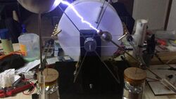
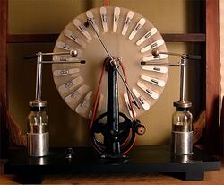
In 1878, the British inventor James Wimshurst started his studies about electrostatic generators, improving the Holtz machine, in a powerful version with multiple disks. The classical Wimshurst machine, that became the most popular form of influence machine, was reported to the scientific community by 1883, although previous machines with very similar structures were previously described by Holtz and Musaeus. In 1885, one of the largest-ever Wimshurst machines was built in England (it is now at the Chicago Museum of Science and Industry). The Wimshurst machine is a considerably simple machine; it works, as all influence machines, with electrostatic induction of charges, which means that it uses even the slightest existing charge to create and accumulate more charges, and repeats this process for as long as the machine is in action. Wimshurst machines are composed of: two insulated disks attached to pulleys of opposite rotation, the disks have small conductive (usually metal) plates on their outward-facing sides; two double-ended brushes that serve as charge stabilizers and are also the place where induction happens, creating the new charges to be collected; two pairs of collecting combs, which are, as the name implies, the collectors of electrical charge produced by the machine; two Leyden Jars, the capacitors of the machine; a pair of electrodes, for the transfer of charges once they have been sufficiently accumulated. The simple structure and components of the Wimshurst Machine make it a common choice for a homemade electrostatic experiment or demonstration, these characteristics were factors that contributed to its popularity, as previously mentioned.[9]
In 1887, Weinhold modified the Leyser machine with a system of vertical metal bar inductors with wooden cylinders close to the disk for avoiding polarity reversals. M. L. Lebiez described the Lebiez machine, that was essentially a simplified Voss machine (L'Électricien, April 1895, pp. 225–227). In 1893, Louis Bonetti patented a machine with the structure of the Wimshurst machine, but without metal sectors in the disks.[10][11] This machine is significantly more powerful than the sectored version, but it must usually be started with an externally applied charge.
Pidgeon machine
In 1898, the Pidgeon machine was developed with a unique setup by W. R. Pidgeon. On October 28 that year, Pidgeon presented this machine to the Physical Society after several years of investigation into influence machines (beginning at the start of the decade). The device was later reported in the Philosophical Magazine (December 1898, pg. 564) and the Electrical Review (Vol. XLV, pg. 748). A Pidgeon machine possesses fixed electrostatic inductors arranged in a manner that increases the electrostatic induction effect (and its electrical output is at least double that of typical machines of this type [except when it is overtaxed]). The essential features of the Pidgeon machine are, one, the combination of the rotating support and the fixed support for inducing charge, and, two, the improved insulation of all parts of the machine (but more especially of the generator's carriers). Pidgeon machines are a combination of a Wimshurst Machine and Voss Machine, with special features adapted to reduce the amount of charge leakage. Pidgeon machines excite themselves more readily than the best of these types of machines. In addition, Pidgeon investigated higher current "triplex" section machines (or "double machines with a single central disk") with enclosed sectors (and went on to receive British Patent 22517 (1899) for this type of machine).
Multiple disk machines and "triplex" electrostatic machines (generators with three disks) were also developed extensively around the turn of the 20th century. In 1900, F. Tudsbury discovered that enclosing a generator in a metallic chamber containing compressed air, or better, carbon dioxide, the insulating properties of compressed gases enabled a greatly improved effect to be obtained owing to the increase in the breakdown voltage of the compressed gas, and reduction of the leakage across the plates and insulating supports. In 1903, Alfred Wehrsen patented an ebonite rotating disk possessing embedded sectors with button contacts at the disk surface. In 1907, Heinrich Wommelsdorf reported a variation of the Holtz machine using this disk and inductors embedded in celluloid plates (DE154175; "Wehrsen machine"). Wommelsdorf also developed several high-performance electrostatic generators, of which the best known were his "Condenser machines" (1920). These were single disk machines, using disks with embedded sectors that were accessed at the edges.
Van de Graaff
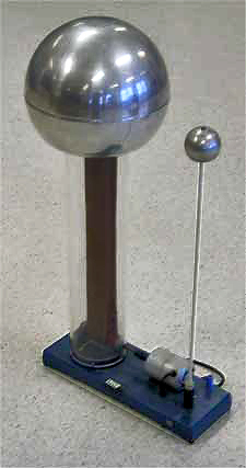
The Van de Graaff generator was invented by American physicist Robert J. Van de Graaff in 1929 at MIT as a particle accelerator.[12] The first model was demonstrated in October 1929. In the Van de Graaff machine, an insulating belt transports electric charge to the interior of an insulated hollow metal high voltage terminal, where it is transferred to the terminal by a "comb" of metal points. The advantage of the design was that since there was no electric field in the interior of the terminal, the charge on the belt could continue to be discharged onto the terminal regardless of how high the voltage on the terminal was. Thus the only limit to the voltage on the machine is ionization of the air next to the terminal. This occurs when the electric field at the terminal exceeds the dielectric strength of air, about 30 kV per centimeter. Since the highest electric field is produced at sharp points and edges, the terminal is made in the form of a smooth hollow sphere; the larger the diameter the higher the voltage attained. The first machine used a silk ribbon bought at a five and dime store as the charge transport belt. In 1931 a version able to produce 1,000,000 volts was described in a patent disclosure.
The Van de Graaff generator was a successful particle accelerator, producing the highest energies until the late 1930s when the cyclotron superseded it. The voltage on open air Van de Graaff machines is limited to a few million volts by air breakdown. Higher voltages, up to about 25 megavolts, were achieved by enclosing the generator inside a tank of pressurized insulating gas. This type of Van de Graaff particle accelerator is still used in medicine and research. Other variations were also invented for physics research, such as the Pelletron, that uses a chain with alternating insulating and conducting links for charge transport.
Small Van de Graaff generators are commonly used in science museums and science education to demonstrate the principles of static electricity. A popular demonstration is to have a person touch the high voltage terminal while standing on an insulated support; the high voltage charges the person's hair, causing the strands to stand out from the head.
Others
Not all electrostatic generators use the triboelectric effect or electrostatic induction. Electric charges can be generated by electric currents directly. Examples are ionizers and ESD guns.
Applications
Gridded ion thruster
EWICON
An electrostatic vaneless ion wind generator, the EWICON, has been developed by The School of Electrical Engineering, Mathematics and Computer Science at Delft University of Technology (TU Delft). Its stands near Mecanoo, an architecture firm. The main developers were Johan Smit and Dhiradj Djairam. Other than the wind, it has no moving parts. It is powered by the wind carrying away charged particles from its collector.[13] The design suffers from poor efficiency.[14]
Dutch Windwheel
The technology developed for EWICON has been reused in the Dutch Windwheel.[15][16]
Air ioniser
Fringe science and devices
These generators have been used, sometimes inappropriately and with some controversy, to support various fringe science investigations. In 1911, George Samuel Piggott received a patent for a compact double machine enclosed within a pressurized box for his experiments concerning radiotelegraphy and "antigravity". Much later (in the 1960s), a machine known as "Testatika" was built by German engineer, Paul Suisse Bauman, and promoted by a Swiss community, the Methernithans. Testatika is an electromagnetic generator based on the 1898 Pidgeon electrostatic machine, said to produce "free energy" available directly from the environment.
See also
- Electrostatic motor
- Electrometer (also known as the "electroscope")
- Electret
- Static electricity
References
- ↑ See:
- Heathcote, N. H. de V. (1950) "Guericke's sulphur globe", Annals of Science, 6 : 293–305. doi:10.1080/00033795000201981
- Zeitler, Jürgen (2011) "Guerickes Weltkräfte und die Schwefelkugel", Monumenta Guerickiana 20/21 : 147–156.
- Schiffer, Michael Brian (2003). Draw the Lightning Down: Benjamin Franklin and Electrical Technology in the Age of Enlightenment. Univ. of California Press. pp. 18-19. ISBN 0-520-24829-5. https://archive.org/details/drawlightningdow00mich.
- ↑ Optics, 8th Query
- ↑ Hauksbee, Francis (1709). Psicho-Mechanical Experiments On Various Subjects. R. Brugis.
- ↑ Pumfrey, Stephen (May 2009). "Hauksbee, Francis (bap. 1660, d. 1713)". Oxford Dictionary of National Biography (online ed.). Oxford University Press. doi:10.1093/ref:odnb/12618. http://www.oxforddnb.com/view/article/12618. Retrieved 2011-12-11. (Subscription or UK public library membership required.)
- ↑ Consult Dr. Carpue's 'Introduction to Electricity and Galvanism', London 1803.
- ↑ Maver, William Jr.: "Electricity, its History and Progress", The Encyclopedia Americana; a library of universal knowledge, vol. X, pp. 172ff. (1918). New York: Encyclopedia Americana Corp.
- ↑ Ronalds, B.F. (2016). Sir Francis Ronalds: Father of the Electric Telegraph. London: Imperial College Press. ISBN 978-1-78326-917-4.
- ↑ Ronalds, B.F. (2016). "Sir Francis Ronalds and the Electric Telegraph". International Journal for the History of Engineering & Technology 86: 42–55. doi:10.1080/17581206.2015.1119481.
- ↑ De Queiroz, A. C (2014). "Operation of the Wimshurst Machine". http://www.coe.ufrj.br/~acmq/whyhow.html.
- MIT (2010). "MIT Physics Demo – The Wimshurst Machine". https://www.youtube.com/watch?v=Zilvl9tS0Og.
- Weisstein, E. W (1996–2007). "Wimshurst Machine – from Eric Weisstein's World of Physics". http://scienceworld.wolfram.com/physics/WimshurstMachine.html.
- Von Slatt, J (2012). "Jake's Wimshurst Machine and How to Build It! (Part 1)". http://steampunkworkshop.com/how-build-wimshurst-influence-machine-part-1/.
- ↑ Bonetti, "Une machine électrostatique, genre Wimshurst, sans secteurs et invisible" [An electrostatic machine of the Wimshurst type, without visible sectors], French patent no. 232,623 (issued: September 5, 1893). See: Description des machines et procédés pour lesquels des brevets d'invention ont été pris … (Descriptions of machines and processes for which patents of invention have been taken … ), 2nd series, vol. 87, part 2 (1893), section: Instruments de précision: Production et transport de l'électricité, page 87.
- ↑ See also:
- (Anon.) (April 14, 1894) "Machines d'induction électrostatique sans secteurs" (Electrostatic induction machines without sectors), La Nature, 22 (1089) : 305–306.
- English translation of La Nature article (above): (Anon.) (May 26, 1894) "Electrostatic induction machines without sectors," Scientific American, 70 (21) : 325-326.
- S. M. Keenan (August 1897) "Sectorless Wimshurst machines," American Electrician, 9 (8) : 316–317
- Instructions for building a Bonetti machine
- G. Pellissier (1891) "Théorie de la machine de Wimshurst" (Theory of Wimshurt's machine), Journal de Physique théoretique et appliquée, 2nd series, 10 (1) : 414–419. On p. 418, French lighting engineer Georges Pellissier describes what is essentially a Bonetti machine: " ... la machine de Wimshurst pourrait, en effet, être construite avec des plateaux de verre unis et des peignes au lieu de brosses aux extrémités des conducteurs diamétraux. L'amorçage au départ devrait être fait à l'aide d'une source étrangère, placée, par example, en face de A1, à l'extérieur." (... Wimshurst's machine could, in effect, be constructed with plain glass plates and with combs in place of brushes at the ends of the diametrical conductors. The initial charging could be done with the aid of an external source placed, for example, opposite and outside of [section] A1 [of the glass disk].) Pellissier then states that "the role of the metallic sectors of the Wimshurst machine seems to be primarily, in effect, to facilitate its automatic starting and to reduce the influence of atmospheric humidity."
- ↑ Van de Graaff, R. J.; Compton, K. T.; Van Atta, L. C. (February 1933). "The Electrostatic Production of High Voltage for Nuclear Investigations". Physical Review (American Physical Society) 43 (3): 149–157. doi:10.1103/PhysRev.43.149. Bibcode: 1933PhRv...43..149V. http://web.ihep.su/dbserv/compas/src/van%20de%20graaff33/eng.pdf. Retrieved August 31, 2015.
- ↑ "EWICON (Electrostatic Wind Energy Converter)". April 13, 2013. http://landartgenerator.org/blagi/archives/2872.
- ↑ How Long Must We Wait for the Bladeless Windmill?
- ↑ Dutch Windwheel 2.0: Herontwerp zonder windenergie?
- ↑ Dutch Windwheel
Further reading
- Gottlieb Christoph Bohnenberger (de): Beschreibung unterschiedlicher Elektrizitätsverdoppler von einer neuen Einrichtung nebst einer Anzahl von Versuchen üb. verschiedene Gegenstände d. Elektrizitätslehre [Description of different electricity-doubler of a new device, along with a number of experiments on various subjects of electricity] Tübingen 1798.
- Holtz, W. (1865). "Ueber eine neue Elektrisirmaschine" (in de). Annalen der Physik und Chemie (Wiley) 202 (9): 157–171. doi:10.1002/andp.18652020911. ISSN 0003-3804. Bibcode: 1865AnP...202..157H. https://babel.hathitrust.org/cgi/pt?id=umn.31951d00326565g;view=1up;seq=177.
- Wilhelm Holtz: the higher charge on insulating surfaces by side pull and the transfer of this principle to the construction of induction machines .. In: Johann Poggendorff, CG Barth (eds): Annals of physics and chemistry. 130, Leipzig 1867, pp. 128–136
- Wilhelm Holtz: The influence machine. In: F. Poske (Eds.): Annals of physics and chemistry. Julius Springer, Berlin 1904 (seventeenth year, the fourth issue).
- O. Lehmann: Dr. J. Frick's physical technique. 2, Friedrich Vieweg und Sohn, Braunschweig 1909, p. 797 (Section 2).
- F. Poske: New forms of influence machines. In: F. Poske (eds) for the physical and chemical education. journal Julius Springer, Berlin 1893 (seventh year, second issue).
- C. L. Stong, "Electrostatic motors are powered by electric field of the Earth". October, 1974. (PDF)
- Oleg D. Jefimenko, "Electrostatic Motors: Their History, Types, and Principles of Operation". Electret Scientific, Star City, 1973.
- G. W. Francis (author) and Oleg D. Jefimenko (editor), "Electrostatic Experiments: An Encyclopedia of Early Electrostatic Experiments, Demonstrations, Devices, and Apparatus". Electret Scientific, Star City, 2005.
- V. E. Johnson, "Modern High-Speed Influence Machines; Their principles, construction and applications to radiography, radio-telegraphy, spark photography, electro-culture, electro-therapeutics, high-tension gas ignition, and the testing of materials". ISBN B0000EFPCO
- Simon, Alfred W. (1 November 1924). "Quantitative Theory of the Influence Electrostatic Generator". Physical Review (American Physical Society (APS)) 24 (6): 690–696. doi:10.1103/physrev.24.690. ISSN 0031-899X. PMID 16576822. Bibcode: 1924PhRv...24..690S.
- J. Clerk Maxwell, Treatise on Electricity and Magnetism (2nd ed.,Oxford, 1881), vol. i. p. 294
- Joseph David Everett, Electricity (expansion of part iii. of Augustin Privat-Deschanel's "Natural Philosophy") (London, 1901), ch. iv. p. 20
- A. Winkelmann, Handbuch der Physik (Breslau, 1905), vol. iv. pp. 50–58 (contains a large number of references to original papers)
- J. Gray, "Electrical Influence Machines, Their Historical Development and Modern Forms [with instruction on making them]" (London, I903). (J. A. F.)
- Silvanus P. Thompson, The Influence Machine from Nicholson – 1788 to 1888, Journ. Soc. Tel. Eng., 1888, 17, p. 569
- John Munro, The Story Of Electricity (The Project Gutenberg Etext)
- A. D. Moore (Editor), "Electrostatics and its Applications". Wiley, New York, 1973.
- Oleg D. Jefimenko (with D. K. Walker), "Electrostatic motors". Phys. Teach. 9, 121–129 (1971).
- Pidgeon, W R (1892). "An Influence-Machine". Proceedings of the Physical Society of London (IOP Publishing) 12 (1): 406–411. doi:10.1088/1478-7814/12/1/327. ISSN 1478-7814. Bibcode: 1892PPSL...12..406P. https://zenodo.org/record/1431481.
- Pidgeon, W R (1897). "An Influence-Machine". Proceedings of the Physical Society of London (IOP Publishing) 16 (1): 253–257. doi:10.1088/1478-7814/16/1/330. ISSN 1478-7814. Bibcode: 1897PPSL...16..253P.
External links
- Electrostatic Generator – Interactive Java Tutorial National High Magnetic Field Laboratory
- "How it works : Electricity". triquartz.co.uk.
 |
