Physics:Longitudinal mode
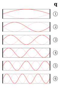
A longitudinal mode of a resonant cavity is a particular standing wave pattern formed by waves confined in the cavity. The longitudinal modes correspond to the wavelengths of the wave which are reinforced by constructive interference after many reflections from the cavity's reflecting surfaces. All other wavelengths are suppressed by destructive interference.
A longitudinal mode pattern has its nodes located axially along the length of the cavity. Transverse modes, with nodes located perpendicular to the axis of the cavity, may also exist.
Simple cavity
A common example of longitudinal modes are the light wavelengths produced by a laser. In the simplest case, the laser's optical cavity is formed by two opposed plane (flat) mirrors surrounding the gain medium (a plane-parallel or Fabry–Pérot cavity). The allowed modes of the cavity are those where the mirror separation distance L is equal to an exact multiple of half the wavelength, λ:
- [math]\displaystyle{ L = q \frac{\lambda}{2} }[/math]
where q is an integer known as the mode order.
In practice, the separation distance of the mirrors L is usually much greater than the wavelength of light λ, so the relevant values of q are large (around 105 to 106). The frequency separation between any two adjacent modes, q and q+1, in a material that is transparent at the laser wavelength, are given (for an empty linear resonator of length L) by Δν:
- [math]\displaystyle{ \Delta\nu = \frac{c}{2nL} }[/math]
where c is the speed of light and n is the refractive index of the material (note: n≈1 in air).
Composite cavity
If the cavity is non-empty (i.e. contains one or more elements with different values of refractive index), the values of L used are the optical path lengths for each element. The frequency spacing of longitudinal modes in the cavity is then given by:
- [math]\displaystyle{ \Delta \nu = \frac{c}{2\sum_i n_i L_i} = \frac{c}{2}\left[ \frac{1}{n_1 L_1 + n_2 L_2 + n_3 L_3 + \ldots} \right] }[/math]
where ni is the refractive index of the i'th element of length Li.
More generally, the longitudinal modes may be found for any type of wave in a cavity by solving the relevant wave equation with the appropriate boundary conditions.
Both transverse and longitudinal waves may have longitudinal modes when confined to a cavity.
The analysis of longitudinal modes is especially important in lasers with single transversal mode, for example, in single-mode fiber lasers. The number of longitudinal modes of such a laser can be estimated as ratio of the spectral width of gain to the spectral separation of longitudinal modes.[1]
Power per longitudinal mode
For lasers with single transversal mode, the power per one longitudinal mode can be significantly increased by the coherent addition of lasers. Such addition allows one to both scale-up the output power of a single-transverse-mode laser and reduce number of longitudinal modes; because the system chooses automatically only the modes which are common for all the combined lasers. The reduction of the number of longitudinal modes determines the limits of the coherent addition. The ability to coherently add one additional laser is exhausted when one longitudinal mode, common for the combined lasers, lies within the spectral width of the gain; a subsequent addition will lead to loss of efficiency of the coherent combination and will not increase the power per longitudinal mode of such a laser.
See also
- Fabry–Pérot interferometer
- Modelocking
- Normal mode
References
- ↑ Helmut, H. Telle; Ureña, Angel González (30 April 2007). Laser Chemistry: Spectroscopy, Dynamics and Applications. Wiley. p. 42. ISBN 9780470059401. https://books.google.com/books?id=F9jZRse023QC.
 |


