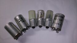
Physics:Glow switch starter
A glow switch starter or glowbottle starter is a type of preheat starter used with a fluorescent lamp. It is commonly filled with neon gas or argon gas and typically contains a bimetallic strip and a stationary electrode. The operating principle is simple, when current is applied, the gas inside ionizes and heats a bimetallic strip which in turn bends toward the stationary electrode thus shorting the starter between the electrodes of the fluorescent lamp. After about a second the starter's bimetallic strip cools and opens the circuit between the electrodes, and the process repeats until the lamp has lit. One disadvantage of glow switch starters is that when the lamp is at the end of its life it will continuously blink on and off until the glow switch starter wears out or an electrode on the fluorescent lamp burns out. Glow starters have a relatively short life, and light fittings enable the starter to be changed easily. Electronic starters, being interchangeable and using the same casing as a glow starter, last for many years.
The glow switch starter was invented by E. C. Dench in 1938.[1]
Operation
- When power is first applied to the circuit, there will be a glow discharge across the electrodes in the starter lamp. This heats up the inert gas (argon or neon) inside the starter and causes one of the bi-metallic strip to bend towards the other terminal.
- When the contacts touch, the two filaments of the fluorescent lamp and the ballast will be switched in series to the supply voltage. The current through the filaments of the tube heats them up and emit electrons into the tube gas by thermionic emission.
- In the starter, the touching contacts short out the voltage sustaining the glow discharge, extinguishing it so the gas inside the starter cools down and no longer heats up the bi-metallic switch, which switches off within a second or two.
- The current through the filaments and the inductive ballast is abruptly interrupted, leaving the full line voltage applied between the filaments at the ends of the tube and generating an inductive kick which provides the high voltage needed to start the lamp. The lamp will fail to strike if the filaments are not hot enough, in which case the cycle repeats; several cycles are usually needed, which causes flickering and clicking during starting (older thermal starters behaved better in this respect). A power factor correction (PFC) capacitor draws leading current from the mains to compensate for the lagging current drawn by the lamp circuit.[2]
- Once the tube strikes, the impinging main discharge keeps the cathodes hot, permitting continued electron emission without the need for the filaments to continue to be heated. The starter switch does not switch on again because the resistance in the tube drops and the voltage across the starter is insufficient to start a glow discharge again.[2]
Automated starters
With automated starters such as glow starters, a failing tube will cycle endlessly, flickering as the lamp quickly goes out because the emission mix is insufficient to keep the lamp current high enough to keep the glow starter open. This runs the ballast at higher temperature. Some more advanced starters time out in this situation, and do not attempt repeated starts until power is reset.[citation needed] Some older systems used a thermal over-current trip to detect repeated starting attempts and disable the circuit until manually reset. The switch contacts in glow starters are subject to wear and inevitably fail eventually, so the starter is manufactured as a plug-in replaceable unit.
References
- ↑ , Edward Charles"Discharge Lamp Circuit" US patent 2200443, published 1940-05-14, issued 1938-11-29, assigned to Westinghouse Electric & Manufacturing Company
- ↑ 2.0 2.1 "Philips Semiconductors, Power Semiconductor Applications" (in en). Philips. 22 November 2009. http://www.nxp.com/documents/application_note/APPCHP8.pdf.
 |


