System on module
A system on a module (SoM) is a board-level circuit that integrates a system function in a single module. It may integrate digital and analog functions on a single board. A typical application is in the area of embedded systems. Unlike a single-board computer, a SoM serves a special function like a system on a chip (SoC). The devices integrated in the SoM typically requires a high level of interconnection for reasons such as speed, timing, bus width etc.. There are benefits in building a SoM, as for SoC; one notable result is to reduce the cost of the base board or the main PCB. Two other major advantages of SoMs are design-reuse and that they can be integrated into many embedded computer applications.[further explanation needed]
History
The acronym SoM has its roots in the blade-based modules. In the mid 1980s, when VMEbus blades used M-Modules,[1] these were commonly referred to as system On a module (SoM).[citation needed] These SoMs performed specific functions such as compute functions and data acquisition functions. SoMs were used extensively by Sun Microsystems, Motorola, Xerox, DEC, and IBM in their blade computers.
Design
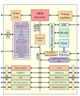
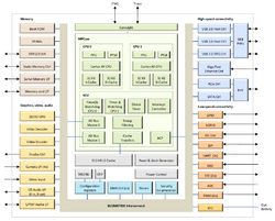
A typical SoM consists of:
- at least one microcontroller, microprocessor or digital signal processor (DSP) core
- multiprocessor systems-on-chip (MPSoCs) have more than one processor core
- memory blocks including a selection of ROM, RAM, EEPROM and/or flash memory
- timing sources
- industry standard communication interfaces such as USB, FireWire, Ethernet, USART, SPI, I²C
- peripherals including counter-timers, real-time timers and power-on reset generators
- analog interfaces including analog-to-digital converters and digital-to-analog converters
- voltage regulators and power management circuits
See also
References
- ANSI/IEEE Std 1014-1987 and ANSI/VITA 1-1994
- 1386-2001 - IEEE Standard for a Common Mezzanine Card Family: CMC
- Standard ANSI/VITA 46.0-2007
- VITA Technologies Hall of Fame - PCI Mezzanine Cards
 |


