Digital antenna array


Digital antenna array (DAA) is a smart antenna with multi channels digital beamforming, usually by using fast Fourier transform (FFT). The development and practical realization of digital antenna arrays theory started in 1962 under the guidance of Vladimir Varyukhin (USSR).
History
The history of the DAA was started to emerge as a theory of multichannel analysis in the 1920s.[1] In the 1940s this theory evolved to the theory of three-channel antenna analyzers.[1]
The implementation of effective signal processing in radars by the end of the 1950s predetermined the use of electronic computers in this field. In 1957, Ben S. Meltont and Leslie F. Bailey published article[2] regarding using algebraic operations for signal processing with the help of electronic circuits or analog computer.[1]
Three years after in 1960 the idea of using high-speed computers to solve directional finding problems was embodied, initially to locate earthquake epicenter. B. A. Bolt was one of the first who implemented this idea in practice.[1][3] Almost simultaneously a similar approach was used by Flinn, a research fellow of the Australian National University.[4]
Despite the fact that in the mentioned experiments the interaction between sensors and computers was implemented with the help of data input cards, such decision was a decisive step on the way of the appearance of the DAA. Then, it was needed only to solve the problem of direct digital data input into the computer from sensors, excluding the step of preparation of punch card and operator assistance as a surplus element.[1] This step for radars theory was made after 1962 in the former USSR conducted with a solution to the problem of superRayleigh resolution of the emission sources.[1]
Digital beamforming
The main approach to digital signal processing in DAA is the "digital beamforming" after Analog-to-digital converters (ADC) of receiver channels or before Digital-to-analog converters (DAC) by transmission.
Digital beamforming of DAA has advantages because the digital signals can be transformed and combined in parallel, to produce different output signals. The signals from every direction can be estimated simultaneously and integrated for a longer time to increasing of signals energy when detecting far-off objects and simultaneously integrated for a shorter time to detecting fast-moving close objects.[6]
Before digital beamforming operation should be used a correction of channels characteristics by a special test source or using the heterodyne signal.[7][8][9] Such correction can be used not only for receiving channels but also in transmission channels of active DAA.[10]
Limitations on the accuracy of estimation of direction of arrival signals and depth of suppression of interferences in digital antenna arrays are associated with jitter in ADCs and DACs.[11][12]
Signal processing methods
Maximum likelihood beamformer
In maximum likelihood beamformer (DML), the noise is modeled as a stationary Gaussian white random processes while the signal waveform as deterministic (but arbitrary) and unknown.
Bartlett beamformer
The Bartlett beamformer is a natural extension of conventional spectral analysis (spectrogram) to the DAA. Its spectral power is represented by
[math]\displaystyle{ \hat{P}_{Bartlett}(\theta)=\boldsymbol v^H \boldsymbol R \boldsymbol v \ \ (1) }[/math].
The angle that maximizes this power is an estimation of the angle of arrival.
Capon beamformer
Capon beamformer, also known as the minimum-variance distortionless response (MVDR) beamforming algorithm,[13] has a power given by
[math]\displaystyle{ \hat{P}_{Capon}(\theta)=\frac{1}{\boldsymbol v^H \boldsymbol R^{-1} \boldsymbol v} \ \ (2) }[/math].
The MVDR/Capon beamformer can achieve better resolution than the conventional (Bartlett) approach, but this algorithm has higher complexity due to the full-rank matrix inversion. Technical advances in GPU computing have begun to narrow this gap and make real-time Capon beamforming possible.[14]
MUSIC beamformer
MUSIC (MUltiple SIgnal Classification) beamforming algorithm starts with decomposing the covariance matrix for both the signal part and the noise part. The eigen-decomposition of is represented by
[math]\displaystyle{ \boldsymbol R = \boldsymbol U_s \boldsymbol \Lambda_s \boldsymbol U_s^H + \boldsymbol U_n \boldsymbol \Lambda_n \boldsymbol U_n^H \ \ (3) }[/math].
MUSIC uses the noise sub-space of the spatial covariance matrix in the denominator of the Capon algorithm
[math]\displaystyle{ \hat{P}_{MUSIC}(\theta)=\frac{1}{\boldsymbol v^H \boldsymbol U_n \boldsymbol U_n^H\boldsymbol v} \ \ (4) }[/math].
Therefore, MUSIC beamformer is also known as subspace beamformer. Compared to the Capon beamformer, it gives much better DOA estimation. As an alternative approach can be used ESPRIT algorithm as well.
Artificial Intelligence
The important trend in evolving digital signal processing for DAA is the use of Artificial Intelligence technologies.[15]
DAA Examples
Radars
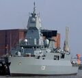
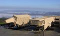
F220 Hamburg with SMART-L
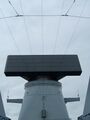
SMART-L onboard F221 Hessen
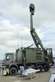
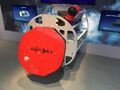
Giraffe AMB, 2007.
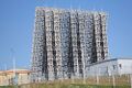
Voronezh-M radar, Lekhtusi.
Radar AN/TPY-2, THAAD
CAPTOR-E, DSEI-2019
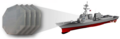
AMDR AN/SPY-6 (digital beamforming[16])


MIMO systems
DAA use to improve the performance of radio communications in MIMO[10] (Massive MIMO) systems.
Sonars and ultrasound sensors
DAA was implemented in a big lot of sonars and medical ultrasound sensors.[14]
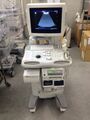
ALOKA SSD-3500SV with 256 channels

See also
References
- ↑ 1.0 1.1 1.2 1.3 1.4 1.5 Slyusar V. I. Origins of the Digital Antenna Array Theory.// International Conference on Antenna Theory and Techniques, 24–27 May 2017, Kyiv, Ukraine. – Pp. 199 - 201 [1]
- ↑ Ben S. Meltont and Leslie F. Bailey, Multiple Signal Correlators.//Geophysics .- July, 1957. - Vol. XXII, No. 3. - Pp. 565-588. - DOI: 10.1190/1.1438390
- ↑ B. A. Bolt. The Revision of Earthquake Epicentres, Focal Depths and Origin-Times using a High-speed Computer.//Geophysical Journal. - 1960, Vol. 3, Issue 4. - Pp. 433 — 440. - DOI: 10.1111/j.1365-246X.1960.tb01716.x.
- ↑ E. A. Flinn. Local earthquake location with an electronic computer.//Bulletin of the Seismological Society of America. - July 1960. - Vol. 50, No. 3. – Pp. 467 - 470
- ↑ Vadym Slyusar. New Matrix Operations for DSP (Lecture). April 1999. - DOI: 10.13140/RG.2.2.31620.76164/1
- ↑ Systems Aspects of Digital Beam Forming Ubiquitous Radar, Merrill Skolnik, 2002, [2]
- ↑ Slyusar, V. I. Correction of characteristics of receiving channels in a digital antenna array by a test source in the near zone// Radioelectronics and Communications Systems. – 2003, VOL 46; PART 1, pages 30-35.[3]
- ↑ Slyusar, V.I. The way of correction of DAA receiving channels characteristics using the heterodyne signal// Proceedings of the III International Conference on Antenna Theory and Techniques, 8–11 September 1999, Sevastopol, pages 244 - 245. [4]
- ↑ Slyusar, V. I., Titov I.V. Correction of smart antennas receiving channels characteristics for 4G mobile communication// Рroceedings of the IV-th International Conference on Antenna Theory and Techniques, 9–12 September 2003. Sevastopol, Pp. 374 – 375. [5]
- ↑ 10.0 10.1 Slyusar, V. I. Titov, I. V. Correction of characteristics of transmitting channels in an active digital antenna array// Radioelectronics and Communications Systems. – 2004, VOL 47; PART 8, pages 9 - 13.[6]
- ↑ Bondarenko M.V., Slyusar V.I.. "Limiting depth of jammer's suppression in a digital antenna array in conditions of ADC jitter.// 5th International Scientific Conference on Defensive Technologies, OTEH 2012. - 18 - 19 September, 2012. - Belgrade, Serbia. - Pp. 495 - 497.". http://slyusar.kiev.ua/OTEH_2012_SLYUSAR.pdf.
- ↑ M. Bondarenko and V.I. Slyusar.. "Influence of jitter in ADC on precision of direction-finding by digital antenna arrays. // Radioelectronics and Communications Systems. - Volume 54, Number 8, 2011.- Pp. 436 - 445.-". doi:10.3103/S0735272711080061. https://link.springer.com/content/pdf/10.3103%2FS0735272711080061.pdf.
- ↑ J. Capon, “High–Resolution Frequency–Wavenumber Spectrum Analysis,” Proceedings of the IEEE, 1969, Vol. 57, pp. 1408–1418
- ↑ 14.0 14.1 Asen, Jon Petter; Buskenes, Jo Inge; Nilsen, Carl-Inge Colombo; Austeng, Andreas; Holm, Sverre (2014). "Implementing capon beamforming on a GPU for real-time cardiac ultrasound imaging". IEEE Transactions on Ultrasonics, Ferroelectrics, and Frequency Control 61 (1): 76–85. doi:10.1109/TUFFC.2014.6689777. PMID 24402897.
- ↑ Svetlana Kondratieva, Elena Ovchinnikova, Pavel Shmachilin, Natalia Anosova. Artificial Neural Networks in Digital Antenna Arrays.//2019 International Conference on Engineering and Telecommunication (EnT). November 2019.
- ↑ Katherine Owens. New Navy destroyer radar conducts first flight test. April 10, 2017.
Further reading
- The estimation and tracking of frequency, Quinn and Hannan, Cambridge University Press 2001.
 |  |

