Engineering:Types of press tools
Press tools are commonly used in hydraulic, pneumatic, and mechanical presses to produce the sheet metal components in large volumes. Generally press tools are categorized by the types of operation performed using the tool, such as blanking, piercing, bending, forming, forging, trimming etc. The press tool will also be specified as a blanking tool, piercing tool, bending tool etc.[1]
Classification of press tools
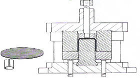
Blanking tool
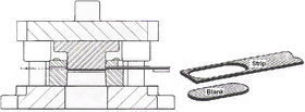
- Blanking is a punching operation in which the entire periphery is cut out and the cutout portion required is known as STAMP OR BLANK.
- When a component is produced with one single punch and die where the entire outer profile is cut in a single stroke the tool is called a blanking tool.
- Blanking is the operation of cutting flat shapes from sheet metal.
- The outer area of metal remaining after a blanking operation is generally discarded as waste.
- Size of blank or product is the size of the die & clearance is given on punch.
- It is a metal cutting operation.
In blanking, metal obtained after cutting is not a scrap if it is usable.
- The size of the blank depends on the size of the die.
- So the size of the die opening is equal to the blank size.
- Clearance is given to the punch.
Piercing tool
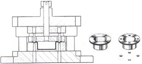
Piercing involves cutting of clean holes with a resulting scrap slug. The operation is called die cutting and can also produce flat components where the die, the shaped tool, is pressed into a sheet material employing a shearing action to cut holes. This method can be used to cut parts of different sizes and shapes in sheet metal, leather and many other materials.
Cut off tool
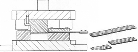
It is a shearing operation in which blanks are separated from a sheet metal strip by cutting the opposite sides of the part in sequence.
Parting off tool
This is similar to a cutoff tool, in that a discrete part is cut from a sheet or strip of metal along a desired geometric path. The difference between a cutoff and a parting is that a cutoff can be nestled perfectly on the sheet metal, due to its geometry. With cutoffs, the cutting of sheet metal can be done over one path at a time and there is practically no waste of material. With partings, the shape can not be nestled precisely. Parting involves cutting the sheet metal along two paths simultaneously. Partings waste a certain amount of material, that can be significant.
Trimming tool
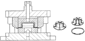
When cups and shells are drawn from flat sheet metal, the edge is left wavy and irregular, due to uneven flow of metal. Shown is flanged shell, as well as the trimmed ring removed from around the edge. While a small amount of Material is removed from the side of a component in trimming tool.[2]
Shaving tool
Shaving removes a small amount of material around the edges of a previously blanked stampings or piercing. A straight, smooth edge is provided and therefore shaving is frequently performed on instrument parts, watch and clock parts and the like. Shaving is accomplished in shaving tools especially designed for the purpose. it is also required proper die clearance
Forming tool
Forming is the operation of deforming a part in curved profile. Forming tools apply more complex forms to work pieces. The line of bend is curved instead of straight, and the metal is subjected to plastic flow or deformation.
Drawing tool
Drawing tools transform flat sheets of metal into cups, shells or other drawn shapes by subjecting the material to severe plastic deformation. Shown in fig is a rather deep shell that has been drawn from a flat sheet. It is an axial elongation through the application of axial force.
This type of Press tool is used to perform only one particular operation therefore classified under stage tools.
Progressive tool
A progressive tool differs from a stage tool in the following respect: in a progressive tool, the final component is obtained by progressing the sheet metal or strip in more than one stage. At each stage, the tool will progressively shape the component towards its final shape, with the final stage normally being cutting-off.
Compound tool
The compound tool differs from progressive and stage tools by the arrangement of the punch and die. It is an inverted tool where blanking and piercing takes place in a single stage and also the blanking punch will act as the piercing die. That means punch will be to the bottom side of the tool and piercing punches to top side of the tool. The burr forms only one side.
Combination tool
In a combination tool, two or more operations such as bending and trimming will be performed simultaneously. Two or more operations such as forming, drawing, extruding, embossing may be combined on the component with various cutting operations like blanking, piercing, broaching and cut off takes place- it can perform a cutting and non-cutting operations in a single tool.
General press tool construction
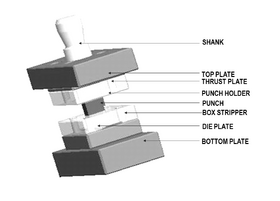
The general press tool construction will have the following elements:
- Shank: It is used as a part for installing the Press tool die in the slide of the press machine with proper alignment.
- Top Plate: It is used to hold top half of the press tool with press slide. It is also called Bolster Plate.
- Punch Back Plate : This plate prevents the hardened punches penetrating into top plate. It is also called Pressure Plate or Backup plate.
- Punch Holder: This plate is used to accommodate the punches of press tool.
- Punches : To perform cutting and non cutting operations either plain or profiled punches are used.
- Die Plate: Die plate will have similar profile of the component where cutting dies usually have holes with land and angular clearance and non cutting dies will have profiles.
- Die Back Plate:This plate prevents the hardened Die inserts penetrating into bottom plate.
- Guide Pillar & Guide Bush : Used for alignment between top and bottom halves of the press tools.
- Bottom plate:It is used to hold bottom half of the press tool with press slide.
- Stripper plate: it is used to strip off the component from punches.
- Strip guides: It is used to guide the strip into the press tool to perform the operation.
Cutting force in press tool
In general, cutting force can be calculated using the formula: CF =L x T x ζmax
Cutting force will be in Newton (N) Where, L = Cut length in mm,(perimeter of profile to be cut) Ex: 40 mm square to be cut will have cut length of 160 mm
T = Sheet metal thickness in mm,
ζmax = Maximum shear strength of sheet metal in MPa
Stripping force
Stripping force is the force required to eject the strip from the punches, which helps the strip to go forward for the next operation Stripping force will be usually 10 to 20 % of cutting force (CF)
Press force
The Press force is the cutting force added to the stripping force: Press Force = Cutting force + Stripping force
Fits in press tools
- Punch holder and Punches =H7/k6
- Punch and Stripper = H7/k6
- Guide Pillar and Guide bush = H7/g6
- Guide bush and Top plate = H7/p6
- Guide pillar and bottom plate = H7/p6
- Dowel and plate = H7/m6
- Dowel holes = H7/m6
References
- ↑ Cyril Donaldson, George H LeCain, V C Goold, Tool design 3rd edition, Tata McGraw-Hill Education, New Delhi.
- ↑ Press tools, BSI British Standards, http://dx.doi.org/10.3403/00311896, retrieved 2023-10-05
 |
