C4 model

The C4 model is a lean graphical notation technique for modeling the architecture of software systems.[1][2] It is based on a structural decomposition (a hierarchical tree structure) of a system into containers and components and relies on existing modelling techniques such as Unified Modeling Language (UML) or entity–relationship diagrams (ERDs) for the more detailed decomposition of the architectural building blocks.
History
The C4 model was created by the software architect Simon Brown between 2006 and 2011 on the roots of Unified Modelling Language (UML) and the 4+1 architectural view model. The launch of an official website under a Creative Commons license[3] and an article[4] published in 2018 popularised the emerging technique.[1]
Overview
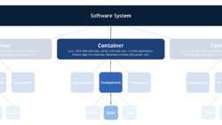
The C4 model documents the architecture of a software system, by showing multiple points of view[5] that explain the decomposition of a system into containers and components, the relationship between these elements, and, where appropriate, the relation with its users.[3]
The viewpoints are organized according to their hierarchical level:[2][3]
- Context diagrams (level 1): show the system in scope and its relationship with users and other systems;
- Container diagrams (level 2): decompose a system into interrelated containers. A container represents an application or a data store;
- Component diagrams (level 3): decompose containers into interrelated components, and relate the components to other containers or other systems;
- Code diagrams (level 4): provide additional details about the design of the architectural elements that can be mapped to code. The C4 model relies at this level on existing notations such as Unified Modelling Language (UML), Entity Relation Diagrams (ERD) or diagrams generated by Integrated Development Environments (IDE).
For level 1 to 3, the C4 model uses 5 basic diagramming elements: persons, software systems, containers, components and relationships. The technique is not prescriptive for the layout, shape, colour and style of these elements. Instead, the C4 model recommends using simple diagrams based on nested boxes in order to facilitate interactive collaborative drawing. The technique also promotes good modelling practices such as providing a title and legend on every diagram, and clear unambiguous labelling in order to facilitate the understanding by the intended audience.
The C4 model facilitates collaborative visual architecting and evolutionary architecture in the context of agile teams where more formal documentation methods and up-front architectural design are not desired.[6]
See also
References
- ↑ 1.0 1.1 Richards, Mark; Ford, Neal (2019). Fundamentals of software architecture: an engineering approach. O'REILLY MEDIA. pp. 293. ISBN 978-1-4920-4342-3. OCLC 1138515057. https://www.worldcat.org/oclc/1138515057. ""some standard are emerging for diagramming software architecture (such as software architect Simon Brown's C4 model or The Open Group Archimate standard)""
- ↑ 2.0 2.1 Enríquez, René (2018). Software Architecture with Spring 5. 0 : Design and Architect Highly Scalable, Robust, and High-Performance Java Applications.. Salazar, Alberto.. Packt Publishing Ltd.. pp. 41–44. ISBN 978-1-78899-673-0. OCLC 1053798657. https://www.worldcat.org/oclc/1053798657.
- ↑ 3.0 3.1 3.2 Brown, Simon. "The C4 model for visualising software architecture". https://c4model.com/.
- ↑ Brown, Simon (2018-06-25). "The C4 Model for Software Architecture" (in en). https://www.infoq.com/articles/C4-architecture-model/.
- ↑ Keeling, Michael. Design it! : from programmer to software architect. Raleigh, North Carolina. ISBN 978-1-68050-345-6. OCLC 1024312521. https://www.worldcat.org/oclc/1024312521.
- ↑ "The Conflict Between Agile and Architecture: Myth or Reality?" (in en). Software Engineering Institute of Carnegie Mellon University. https://resources.sei.cmu.edu/library/asset-view.cfm?assetid=48635.
External links
 |
