Cederbaum's maximum flow theorem
Cederbaum's theorem[1] defines hypothetical analog electrical networks which will automatically produce a solution to the minimum s–t cut problem. Alternatively, simulation of such a network will also produce a solution to the minimum s–t cut problem. This article gives basic definitions, a statement of the theorem and a proof of the theorem. The presentation in this article closely follows the presentation of the theorem in the original publication.
Definitions
Definitions in this article are consistent in all respects with those given in a discussion of the maximum-flow minimum-cut theorem.
Flow graph
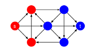
Cederbaum's theorem applies to a particular type of directed graph: G = (V, E). V is the set of nodes. is the a set of directed edges: . A positive weight is associated with each edge: wab: E → R+ . Two of the nodes must be s and t: and .
Flow
Flow, f : E → R+, is a positive quantity associated with each edge in the graph. Flow is constrained by the weight of the associated edge and by the conservation of flow at each vertex as described here.
Current

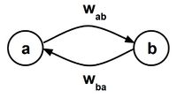
Current is defined as a map for each edge pair to the real numbers, iab : Ep → R. Current maps from the voltage to a range that is determined by the weights of the respective forward and reverse edges. Each edge pair is the tuple consisting of the forward and reverse edges for a given pair of vertices. The current in the forward and reverse directions between a pair of nodes are the additive inverses of one another: iab = −iba . Current is conserved at each interior node in the network. The net current at the and nodes is non-zero. The net current at the node is defined as the input current. For the set of neighbors of the node , :
Voltage
Voltage is defined as a mapping from the set of edge pairs to real numbers, vab : Ep → R. Voltage is directly analogous to electrical voltage in an electrical network. The voltage in the forward and reverse directions between a pair of nodes are the additive inverses of one another: vab = −vba . The input voltage is the sum of the voltages over a set of edges, , that form a path between the and nodes.
s–t cut

An s–t cut is a partition of the graph into two parts each containing one of either or . Where , , , the s–t cut is . The s–t cut set is the set of edges that start in and end in . The minimum s–t cut is the s–t cut whose cut set has the minimum weight. Formally, the cut set is defined as:
Electrical network
An electrical network is a model that is derived from a flow graph. Each resistive element in the electrical network corresponds to an edge pair in the flow graph. The positive and negative terminals of the electrical network are the nodes corresponding to the and terminals of the graph, respectively. The voltage state of the model becomes binary in the limit as the input voltage difference approaches . The behavior of the electrical network is defined by Kirchhoff's voltage and current laws. Voltages add to zero around all closed loops and currents add to zero at all nodes.
Resistive element
A resistive element in the context of this theorem is a component of the electrical network that corresponds to an edge pair in the flow graph.
iv characteristic

The characteristic is the relationship between current and voltage. The requirements are:
(i) Current and voltage are continuous function with respect to one another.
(ii) Current and voltage are non-decreasing functions with respect to one another.
(iii) The range of the current is limited by the weights of the forward and reverse edges corresponding to the resistive element. The current range may be inclusive or exclusive of the endpoints. The domain of the voltage is exclusive of the maximum and minimum currents:
- iab : R → [−wab,wba] or (−wab,wba] or [−wab,wba) or (−wab,wba)
- vab : (−wab,wba) → R
Statement of theorem
The limit of the current Iin between the input terminals of the electrical network as the input voltage, Vin approaches , is equal to the weight of the minimum cut set XC .
Proof
Claim 1 Current at any resistive element in the electrical network in either direction is always less than or equal to the maximum flow at the corresponding edge in the graph. Therefore, the maximum current through the electrical network is less than the weight of the minimum cut of the flow graph:
Claim 2 As the input voltage approaches infinity, there exists at least one cut set such that the voltage across the cut set approaches infinity.
This implies that:
Given claims 1 and 2 above:
Related Topics
The existence and uniqueness of a solution to the equations of an electrical network composed of monotone resistive elements was established by Duffin.[2]
Application
Cederbaum's maximum flow theorem is the basis for the Simcut algorithm.[3] [4]
References
- ↑ Cederbaum, I. (August 1962). "On the optimal operation of communication nets". Journal of the Franklin Institute 274: 130-141.
- ↑ Duffin, R. J. (1947). "Nonlinear networks. IIa.". Bull. Amer. Math. Soc. 10: 963--971.
- ↑ Yim, P.J.: "Method and System for Image Segmentation," United States Patent US8929636, January 6, 2016
- ↑ Yim, P.J.: "Method and System for Image Segmentation Using a Directed Graph," United States Patent US9984311, May 29, 2018
 |
