Computer network diagram
A computer network diagram is a schematic depicting the nodes and connections amongst nodes in a computer network or, more generally, any telecommunications network. Computer network diagrams form an important part of network documentation.
Symbolization

Readily identifiable icons are used to depict common network appliances, e.g. routers, and the style of lines between them indicates the type of connection. Clouds are used to represent networks external to the one pictured for the purposes of depicting connections between internal and external devices, without indicating the specifics of the outside network. For example, in the hypothetical local area network pictured to the right, three personal computers and a server are connected to a switch; the server is further connected to a printer and a gateway router, which is connected via a WAN link to the Internet.[1]
Depending on whether the diagram is intended for formal or informal use, certain details may be lacking and must be determined from context. For example, the sample diagram does not indicate the physical type of connection between the PCs and the switch, but since a modern LAN is depicted, Ethernet may be assumed. If the same style of line was used in a WAN (wide area network) diagram, however, it may indicate a different type of connection.
At different scales diagrams may represent various levels of network granularity. At the LAN level, individual nodes may represent individual physical devices, such as hubs or file servers, while at the WAN level, individual nodes may represent entire cities. In addition, when the scope of a diagram crosses the common LAN/MAN/WAN boundaries, representative hypothetical devices may be depicted instead of showing all actually existing nodes. For example, if a network appliance is intended to be connected through the Internet to many end-user mobile devices, only a single such device may be depicted for the purposes of showing the general relationship between the appliance and any such device.
Cisco symbolization
Cisco uses its own brand of networking symbols. Since Cisco has a large Internet presence and designs a broad variety of network devices, its list of symbols ("Network Topology Icons") is exhaustive.[2]
Topology
The physical network topology can be directly represented in a network diagram, as it is simply the physical graph represented by the diagrams, with network nodes as vertices and connections as undirected or direct edges (depending on the type of connection).[3] The logical network topology can be inferred from the network diagram if details of the network protocols in use are also given.
Gallery
-
 Virtual Private Network
 -
 Enterprise private network
 -
 Overlay network collapsed
 -
 Overlay network broken-up
 -
 xDSL to Internet connectivity
 -
 Triple play illustration
 -
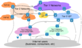 Internet Distribution and Core
 -
 Internet, Access to core


See also
References
- ↑ Stephen McQuerry (29 May 2008). "Chapter 1: Building a Simple Network". Network World. http://www.networkworld.com/subnets/cisco/053008-ch1-ccna-prep-library.html. Retrieved 16 May 2012.
- ↑ "Network Topology Icons". Cisco. http://www.cisco.com/web/about/ac50/ac47/2.html. Retrieved 16 May 2012.
- ↑ "Network Infrastructure". Microsoft. 2012-07-18. https://technet.microsoft.com/en-us/library/cc961037.aspx. Retrieved 16 May 2012.
 |  |
