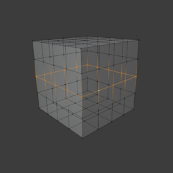
Edge loop
An edge loop, in computer graphics, can loosely be defined as a set of connected edges across a surface. (More specifically, the edges can form an edge ring and be one side of a face loop.) Usually, the last edge meets again with the first edge, thus forming a loop. The set or string of edges can, for example, be the outer edges of a flat surface or the edges surrounding a 'hole' in a surface.

In a stricter sense, an edge loop is defined as a set of edges where the loop follows the middle edge in every 'four way junction'.[1] The loop will end when it encounters another type of junction (three or five way, for example). Take an edge on a mesh surface for example, say at one end of the edge it connects with three other edges, making a four way junction. If you follow the middle 'road' each time, you would either end up with a completed loop or the edge loop would end at another type of junction.
Edge loops are especially practical in organic models which need to be animated. In organic modeling, edge loops play a vital role in proper deformation of the mesh.[2] A properly modeled mesh will take into careful consideration the placement and termination of these edge loops. Generally, edge loops follow the structure and contour of the muscles that they mimic. For example, in modeling a human face, edge loops should follow the orbicularis oculi muscle around the eyes and the orbicularis oris muscle around the mouth. The hope is that by mimicking the way the muscles are formed, they also aid in the way the muscles are deformed by way of contractions and expansions. An edge loop closely mimics how real muscles work, and if built correctly, provides control over contour and silhouette in any position.
"Edge loop" was first coined as a modelling term in 1999 by 3D artist Bay Raitt, in an article called Digital sculpting techniques for 3D Design magazine.
References
- ↑ "Edge Loop". CG Society. Archived from the original on 2011-03-24. https://web.archive.org/web/20110324081434/http://wiki.cgsociety.org/index.php/Edge_Loop. Retrieved 2017-07-04.
- ↑ Modeling With Edge Loops , Zoomy.net
External links
- "First appearance of Edge loops in an 3D world magazine article 'Digital Sculpting techniques'". Bay Raitt. Archived from the original on 2017-05-16. https://web.archive.org/web/20170516170023/http://www.theminters.com/misc/articles/derived-surfaces/derived-surfaces.pdf. Retrieved 2017-04-16.
- "Edge Loop". CG Society. Archived from the original on 2011-03-24. https://web.archive.org/web/20110324081434/http://wiki.cgsociety.org/index.php/Edge_Loop. Retrieved 2017-07-04.
- [1], Another Description from 2000
 |
