Engineering:Active rectification

Active rectification, or synchronous rectification, is a technique for improving the efficiency of rectification by replacing diodes with actively controlled switches such as transistors, usually power MOSFETs or power BJTs.[1] Historically, vibrator driven switches or motor-driven commutators have also been used for mechanical rectifiers and synchronous rectification.[2]
Motivation

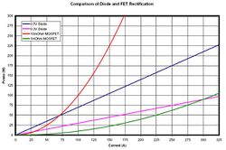
The constant voltage drop of a standard p-n junction diode is typically between 0.7 V and 1.7 V, causing significant power loss in the diode. Electric power depends on current and voltage: the power loss rises proportional to both current and voltage.
In low voltage converters (around 10 volts and less), the voltage drop of a diode (typically around 0.7 to 1 volt for a silicon diode at its rated current) has an adverse effect on efficiency. One classic solution replaces standard silicon diodes with Schottky diodes, which exhibit very low voltage drops (as low as 0.3 volts). However, even Schottky rectifiers can be significantly more lossy than the synchronous type, notably at high currents and low voltages.
When addressing very low-voltage converters, such as a buck converter power supply for a computer CPU (with a voltage output around 1 volt, and many amperes of output current), Schottky rectification does not provide adequate efficiency. In such applications, active rectification becomes necessary.[1]
Description
Replacing a diode with an actively controlled switching element such as a MOSFET is the heart of active rectification. MOSFETs have a constant very low resistance when conducting, known as on-resistance (RDS(on)). They can be made with an on-resistance as low as 10 mΩ or even lower. The voltage drop across the transistor is then much lower, meaning a reduction in power loss and a gain in efficiency. However, Ohm's Law governs the voltage drop across the MOSFET, meaning that at high currents, the drop can exceed that of a diode. This limitation is usually dealt with either by placing several transistors in parallel, thereby reducing the current through each individual one, or by using a device with more active area (on FETs, a device-equivalent of parallel).
The control circuitry for active rectification usually uses comparators to sense the voltage of the input AC and open the transistors at the correct times to allow current to flow in the correct direction. The timing is very important, as a short circuit across the input power must be avoided and can easily be caused by one transistor turning on before another has turned off. Active rectifiers also clearly still need the smoothing capacitors present in passive examples.
Using active rectification to implement AC/DC conversion allows a design to undergo further improvements (with more complexity) to achieve an active power factor correction, which forces the current waveform of the AC source to follow the voltage waveform, eliminating reactive currents and allowing the total system to achieve greater efficiency.
Ideal diode
A MOSFET actively controlled to act as a rectifier—actively turned on to allow current in one direction but actively turned off to block current from flowing the other direction—is sometimes called an ideal diode. Using ideal diodes rather than a standard diodes for solar electric panel bypass, reverse-battery protection, or bridge rectifier reduces the amount of power dissipated in those diodes, improving efficiency and reducing the size of the PC board and weight of the heat sink required to deal with that power dissipation.[3][4][5][6][7][8]
Such a MOSFET-based ideal diode is not to be confused with an op-amp based super diode.
Construction
See H-bridge.
References
- ↑ 1.0 1.1 Ali Emadi (2009). Integrated power electronic converters and digital control. CRC Press. pp. 145–146. ISBN 978-1-4398-0069-0. https://books.google.com/books?id=phX659AzaxUC&pg=PA145.
- ↑ Maurice Agnus Oudin (1907). Standard polyphase apparatus and systems (5th ed.). Van Nostrand. p. 236. https://books.google.com/books?id=GcMJAAAAIAAJ&pg=PA236&dq=%22synchronous+rectifier%22+commutator&hl=en&ei=kTL8TOjoE5S4sQOgxMj3DQ&sa=X&oi=book_result&ct=result&resnum=4&ved=0CDkQ6AEwAw#v=onepage&q=%22synchronous%20rectifier%22%20commutator&f=false.
- ↑ "Ideal Diode for Solar Panel Bypass".
- ↑ "Ideal Diode Bridge Controller".
- ↑ "Ideal Diode Bridge Controller Minimizes Power Loss & Heat in PoE Powered Devices"
- ↑ "Reverse-Current Circuitry Protection".
- ↑ "Reverse Current/Battery Protection Circuits".
- ↑ "Reverse Power Protection using Power MOSFETs".
Further reading
- T. Grossen, E. Menzel, J.J.R. Enslin. (1999) Three-phase buck active rectifier with power factor correction and low EMI. IEE Proceedings - Electric Power Applications, Vol. 146, Iss. 6, Nov. 1999, pp. 591–596. Digital Object Identifier:10.1049/ip-epa:19990523.
- W. Santiago, A. Birchenough. (2005). Single Phase Passive Rectification versus Active Rectification Applied to High Power Stirling Engines. AIAA 2005-5687.
de:Gleichrichter#Synchrongleichrichter
