Engineering:Airbag launching
Airbag launching refers to a method to launch vessels with marine air bags. It is a methodology for ship launching utilizing air bags.[1]
The Xiao Qinghe shipyard launched a tank barge with marine airbags on January 20, 1981, and it is known as the first use of marine airbags.
This kind of ship launching method has the advantages of requiring less permanent infrastructure, risk, and cost. The airbags provide support to the hull of the ship, air bags rolling motion take a vessel launch into water, thus it is arguably safer than other options like sideways launching.
Unlike most other launching methods that are fixed infrastructures, airbag launching has relatively less limitations and can be used in versatile ways.[2] It overcomes the disadvantage of fixed track launching in which capacity of shipbuilding and ship repairing is limited by the fixed infrastructures especially in small and medium-sized shipyards.[3]
Airbags
Ship launching airbags are specialized air bags that are used for launching marine vessels. These air bags are made of synthetic-tire-cord reinforcement layers and rubber layers,[4] and are also known as marine airbags. They were invented in 1980.[citation needed] The first known use of marine airbags occurred on January 20, 1981, with the launch of a tank barge from the Xiao Qinghe shipyard. From then on, more and more shipyards, especially in China and Southeast Asia, began to use air bags to launch small and medium-sized vessels.
In recent years, higher strength materials have been used in air bag production, allowing them to have much more bearing capacity. Hence, they have begun to be used at the launchings of larger vessels. In October 2011, the successful launch of one vessel with a deadweight tonnage (DWT) of 75000 tonnes set a world record for ship launches utilizing air bags.[citation needed] The following year, on June 6, 2012, the ship "He Ming" (IMO number 9657105), with a DWT of 73541 tonnes, total length of 224.8m, breadth of 34m, and depth of 18.5m, also launched successfully using air bags.[5]
Air bag structure
Marine air bags consist of three parts:
- Air bag body: the main, cylindrical part of the air bag after being fully inflated with compressed air,
- Air bag heads: conical parts connecting the body and the mouths of the air bag, and
- Air bag mouths: either metal valves mounted on both ends of the air bag for inflating with air or a valve on one end and a metal lug on the other end used to haul the air bag.
Air bag size and model
Size
The diameter of an air bag varies; sizes include 0.8 m, 1.0 m, 1.2 m, 1.5 m, 1.8 m, etc.
The length of an air bag is specified by the customer when it is manufactured.
Model
Air bags are commonly divided into three to six tire-cord reinforcement layers. There can be more layers, though there are normally less than ten.
Air bag bearing capacity
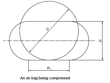
The maximum load carrying capacity of an air bag, which is the maximum load under which it will suffer no permanent deformation or damage, can be found as follows:
Let:
[math]\displaystyle{ D }[/math] be the original diameter of the air bag
[math]\displaystyle{ H }[/math] be the height of the compressed air bag
[math]\displaystyle{ W_{1} }[/math] be the width of the air bag contacting the ship bottom
[math]\displaystyle{ P_{1} }[/math] be the internal pressure of the air bag
[math]\displaystyle{ L }[/math] be the effective length of the air bag
Given these variables, [math]\displaystyle{ \text{bearing capacity} = P_{1} \times W_{1} \times L }[/math]
Air bag materials
Ship launching air bags are constructed of synthetic-tire-cord layers; inner and outer rubber layers are sometimes added. All materials used are vulcanized.
Air bag test
Air tightness test: Without carrying any load, fill the air bag till the internal pressure of the air bag reaches rated working pressure. After 1 hour. The pressure loss should be less than 5% of initial pressure.
Bursting test: Fill the air bag with water until the air bag bursts. The water pressure at the time of bursting shall be no less than three times of rated working pressure.[4]
The arrangements of air bags
Launching type
Based on the ship shapes, the ship may be launched, using air bags, by either end launching type or side launching type
End launching type
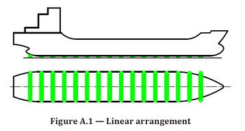
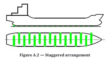
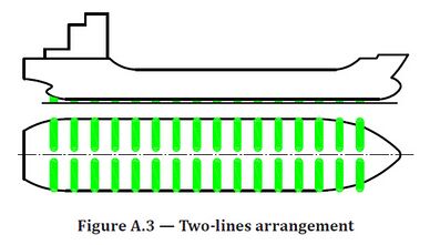
There are three ways to arrange air bags when using the end launching type. They are (1) linear arrangement (see Figure A.1), (2) staggered arrangement (see Figure A.2), and (3) two-lines arrangement (see Figure A.3). As for which arrangement to use, it will depend on the ship's width and the length of the air bags.
When the ship's width is not greater than the effective length of the air bags, the linear arrangement shall be selected
When the ship's width is greater than the effective length of an air bag and less than the effective length of two air bags, the staggered arrangement can be selected.
When the ship's width is greater than the combined effective length of two air bags, or for special ship such as catamaran HSC or split hopper barge, the two lines arrangement shall be selected. The distance between the near ends of two air bags is greater than 0,2 m.
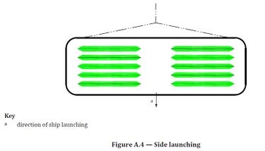
Side launching type
For small flat-bottom ships, the side launching method may be utilized (see Figure A.4)
Air bags quantity
Air bags shall meet the requirements of ISO 14409[4]
According to the weight of the ship being launched, the quantity of the air bags needed for this operation must be calculated in accordance with Formula (1):
- [math]\displaystyle{ N=K_1\frac{Qg}{C_b*R*L_d}\quad\quad\quad(1) }[/math]
where
N is the quantity of air bags used for ship launching;
K1 is a coefficient, in general, K1 ≥ 1,2;
Q is the weight of the ship (ton);
g is acceleration of gravity (m/s2), g = 9,8;
Cb is the block coefficient of the ship being launched;
R is the allowable unit bearing capacity of the air bags (kN/m);
Ld is the contact length between the bottom of the ship and the body of the air bag at the midship section (m).
For ship shifting, 2 to 4 additional air bags shall be made ready and available.
The centre to centre distance between two neighbouring air bags should be less than or equal to that found in Formula (2) and equal to or be greater than that found in Formula (3).
- [math]\displaystyle{ \begin{align} &L/(N-1)\leq6k\quad\quad\quad\quad\quad\quad(2)\\ &L/(N-1)\geq\pi D/2+0,3\quad\quad(3) \end{align} }[/math]
where
L is the actual length of the ship bottom that can make contact with the air bags (m);
N is the quantity of air bags used for ship launching;
k is a coefficient, k = 1 for steel ships, k = 0,8 for wooden, aluminium and glass-fibre-reinforced ships;
D is the nominal diameter of air bags (m).
Slipway
The gradient and the length of the slipway shall be determined according to the size of the ship and the hydrological condition of the area water.
The bearing capacity of the slipway shall be at least twice as strong as the working pressure of air bags.
For ships of more than 3 000 tons of length, more than 120m,the slipway shall be constructed with reinforced concrete and the height difference between the right and left sides shall be less than 20 mm. For ships of more than 1 000 tons but less than or equal to 3 000 tons in weight, or more than 90 m but less than or equal to 120 m in length, the slipway shall be constructed with cement concrete and the height difference between the right and left sides shall be less than 50 mm. For ships of not more than 1 000 tons in weight or not more than 90 m in length, the slipway may be an earthen slope and shall be compacted even by rollers. The height difference between the right and left sides shall be less than 80 mm.
The main slipway shall enable the ship to glide automatically when the ship is off the tow. The auxiliary slipway shall be determined according to the ship type, the water level at time of launching, the diameter of the air bags, and the safety requirements.
Towing arrangement
A windlass shall be used to control the movement of the ship. Tow system that comprises windlass, steel wire rope and pulley set shall be securely fastened to the ground anchor in front of the berth.
In general, a slow windlass shall be selected for ship launching. The veering speed of the windlass shall be 9 m/min to 13 m/min.
The forces of the windlass and the steel wire rope should be calculated carefully by technicians of ship yards or air bags company.
References
- ↑ ISO 17682-2013 Ships and marine technology — Methodology for ship launching utilizing air bags
- ↑ "ShipLaunching.org - Ship Repair & Launching Innovation" (in en-US). http://www.shiplaunching.org/.
- ↑ "Rubber Ship Launching Airbag - Max Groups Marine" (in en-US). Max Groups Marine. http://max-groups.com/products/rubber-ship-launching-airbag-marine-airbag/.
- ↑ 4.0 4.1 4.2 ISO14409-Ships and marine technology of Ship launching air bags
- ↑ "He Ming". https://www.marinetraffic.com/en/ais/details/ships/shipid:649866/mmsi:414124000/imo:9657105/vessel:HE_MING. Retrieved 2018-06-19.
- ↑ "荣成神飞船舶6200吨成品油轮-SF601下水". http://www.imarine.cn/thread-568191-1-1.html.
 |

