Engineering:Direct part marking

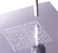
Direct part marking (DPM) is a process to permanently mark parts with product information including serial numbers, part numbers, date codes, and barcodes. This is done to allow the tracking of parts through the full life cycle.
The interpretation of 'permanent' often depends on the context the part is used. In the aerospace industry an aircraft part may be in service for over 30 years. Within telecom and computer industries the life cycle may only last a few years.
DPM is often used by automotive, aerospace, and electronic manufacturers to facilitate a reliable identification of their parts. This can assist in data logging for safety, warranty issues and satisfy regulatory requirements. Also the United States Department of Defense demands a physical mark on tangible assets in conjunction with the Item Unique Identification.
Barcode types
There are many ways to encode an information to a machine-readable code. The preferred codes are the Data Matrix[1] and the QR Code. Data Matrix is used by Motorola.[2] It is also preferred by NASA to mark parts. In the automotive industries also the QR Code is used. This is founded in the fact that this code was initially developed by Denso Wave (a global automotive components manufacturer) for tracking parts in vehicle manufacturing.
Marking methods
Methods to produce a permanent mark on parts are:
- Indenting
- Embossing
- Coining
- Abrasive blasting
- Adhesive dispensing
- Cast, forge or mold
- Dot peen
- Scribe
- Electro-chemical etching
- Embroidery
- Engraving/milling
- Laser marking
- LaserShot peening
- Liquid metal jet
- Stencil (mechanical cut, photo process, laser cut)
Other methods like manual metal stamp, vibro-etch and embossing were not suitable to successfully apply micro size (1/32- to 15/64-inch square), high density machine-readable symbols.[3]
Marking method selection factors
The marking method depends on a number of different factors:
- Part function
Non-intrusive marking methods are recommended for parts used in safety critical applications like aircraft engines or high pressure and high stress systems. - Part geometry
It is more difficult to place a Data Matrix on a curved surface than it is on a flat surface. - Surface
Highly polished metal surfaces should be textured to reduce glare prior to marking. The textured area should extend one symbol width beyond the borders of marking. - Part Size
When a 2D Symbol is used, the size of the part is not a relevant factor as the available marking area is reduced to below 1/4 inch square. - Operating environment / age life
It should be controlled, if the used marking method can survive in its intended environment and remain readable for the life cycle of the part. - Surface roughness / Finish
A rough surface is more challenging for a 2D barcode as the data elements can be recognized appropriately. The surface roughness levels should be limited to 8 micro-inches for dot-peen marking, laser and scribe systems can make a readable mark in rougher surfaces. The laser systems burn a "quiet zone" first and then the 2D code. The scribe method provides a high resolution 2D mark that makes the part readily readable in most cast surfaces.[4] - Surface thickness
Surface thickness must be taken into account when applying intrusive markings to prevent deformation or excessive weakening of the part. In most applications the marking depth should not exceed 1/10 the thickness of the part.
Standards and regulations
Notes and references
- ↑ Andreeta, M. R. B.; Cunha, L. S.; Vales, L. F.; Caraschi, L. C.; Jasinevicius, R. G. (2011). "Bidimensional codes recorded on an oxide glass surface using a continuous wave CO2 laser". Journal of Micromechanics and Microengineering 21 (2): 025004. doi:10.1088/0960-1317/21/2/025004. Bibcode: 2011JMiMi..21b5004A.
- ↑ http://www.mmh.com/article/CA6437021.html Direct part marking: The next hot trend in automatic identification
- ↑ NASA.gov NASA-STD-6002D
- ↑ [Scribe 2D code on cast surfaces]http://columbiamt.com/CMT-Square-Dot-Marking/Cast_Surface.html
 |
