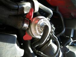
Engineering:Blowoff valve
A blowoff valve (also called dump valve or compressor bypass valve) is a pressure release system present in most petrol turbocharged engines. Blowoff valves are used to reduce pressure in the intake system as the throttle is closed, thus preventing compressor surge.[1]
Design

A key function of blowoff valves is to prevent compressor surge, a phenomenon that would otherwise occur as the throttle is closed in a turbocharged engine. If the turbocharger's compressor wheel is spinning at high speed when the throttle is suddenly closed (such as during a gear change), the flow reduces beyond the surge line of the compressor. At this point the change in pressure across the compressor reduces, leading to a collapse in flow and possibly even flow reversal and a collapse in plenum pressure.[2] As the compressor is still spinning at high speed, once the flow has reduced sufficiently, the change in pressure across the compressor begins to rise and flow is re-established into the plenum.[1][3] This rapid cycle of pressurisation and depressurisation repeats until the compressor has slowed sufficiently or the throttle is re-opened. The sound produced by compressor surge is called turbo flutter and the repeated, high speed cycling will cause a cyclic torque on the compressor and may lead to increased stresses on the bearings and compressor impeller.[2]
A blowoff valve is designed to release pressure in the intake system when the throttle is closed. A "recirculating" type blowoff valve releases the pressurised air back into the non-pressurized section of the intake (i.e. upstream of the turbocharger), while an "atmospheric venting" type blowoff valve dumps the air directly into the atmosphere.
Operation
A vacuum hose connected to the intake manifold downstream of the throttle provides a reference pressure for the blowoff valve.
When the throttle is open, the air pressure on both sides of the blowoff valve's piston is equal, therefore the spring holds the valve closed. As the throttle closes, the pressure in the intake manifold drops below the pressure upstream of the throttle, which causes the valve to open. This allows the excess pressure from the turbocharger to be released into either the atmosphere or the intake manifold.
Intake air metering
In the case where an airflow sensor is present upstream from the blowoff valve and the blowoff valve vents to atmosphere, the fuel injection system is unaware that some of the intake air has been vented instead of going into the cylinders. This volume of vented air is no longer relevant to the engine, however it is still included in the calculations for the required amount of fuel, which causes excess fuel to be injected and therefore the engine briefly operates with a fuel-rich mixture after each blowoff valve actuation. Effects of this rich running can include fouling the spark plugs, damaging the catalytic converter, stalling and hesitation when the throttle is opened.
One method to avoid this issue is by locating the airflow sensor downstream of the blowoff valve (known as a blow-through setup, as opposed to the traditional draw-through setup). By using a blow-through method, the MAF won't be affected by the blowoff valve opening, since the pressure is vented before the air reaches the MAF.
Other solutions include using a blowoff valve that recirculates the air back into the intake or using a manifold absolute pressure sensor (instead of an airflow sensor) to determine the amount of fuel required.
See also
References
- ↑ 1.0 1.1 "All you ever needed to know about blow-off valves" (in en-gb). http://www.gfb.com.au/tech/tech-articles/62-all-you-ever-needed-to-know-about-blow-off-valves.
- ↑ 2.0 2.1 "What is compressor surge?" (in en). https://www.turbobygarrett.com/turbobygarrett/compressor_surge.
- ↑ Xue, Xiang; Wang, Tong; Zhang, Tongtong; Yang, Bo (2018). "Mechanism of stall and surge in a centrifugal compressor with a variable vaned diffuser". Chinese Journal of Aeronautics 31 (6): 1222–1231. doi:10.1016/j.cja.2018.04.003.
Further reading
- Allard, Alan. Turbocharging and Supercharging. Cambridge, England: Patrick Stevens Limited, 1982.
- Gorla, Rama, and Khan, Aijaz. Turbomachinery Design and Theory. New York, New York: Marcel Dekker, 2003.
- Society of Automotive Engineers. Turbochargers and Turbocharged Engines. Warrendale, PA, 1979.
- Watson, N, and Janota, N. Turbocharging the Internal Combustion Engine. London, England: Macmillan Press Ltd, 1982.
de:Turbolader#Umluftventil
 |


