Engineering:Wastegate
A wastegate is a valve that controls the flow of exhaust gases to the turbine wheel in a turbocharged engine system.[1]
Diversion of exhaust gases regulates the turbine speed, which in turn regulates the rotating speed of the compressor. The primary function of the wastegate is to regulate the maximum boost pressure in turbocharger systems, to protect the engine and the turbocharger. One advantage of installing a remote mount wastegate to a free-float (or non-wastegate) turbo includes an allowance for a smaller area over radius (A/R) turbine housing, resulting in less lag time before the turbo begins to spool and create boost.[2] One of the earliest usage of a modern wastegate was in the Saab 99 Turbo 1978, presented in 1977.[3]
Wastegate types
External
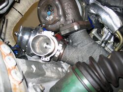
An external wastegate is a separate self-contained mechanism typically used with turbochargers that do not have internal wastegates. An external wastegate requires a specially constructed turbo manifold with a dedicated runner going to the wastegate. The external wastegate may be part of the exhaust housing itself. External wastegates are commonly used for regulating boost levels more precisely than internal wastegates in high power applications, where high boost levels can be achieved. External wastegates can be much larger since there is no constraint of integrating the valve or spring into the turbocharger and turbine housing. It is possible to use an external wastegate with an internally gated turbocharger. This can be achieved through a specially designed bracket that easily bolts on and restricts the movement of the actuator arm, keeping it from opening. Another route involves welding the internal wastegate shut which permanently keeps it from opening, but failure of the weld can allow it to open again.
External wastegates generally use a valve similar to the poppet valve found in the cylinder head. However they are controlled by pneumatics rather than a camshaft and open in the opposite direction. External wastegates can also use a butterfly valve, though that is far less common.
Internal
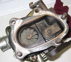
An internal wastegate is a built-in bypass valve and passage within the turbocharger housing which allows excess exhaust pressure to bypass the turbine into the downstream exhaust. Control of the internal wastegate valve by a pressure signal from the intake manifold is identical to that of an external wastegate. Advantages include simpler and more compact installation, with no external wastegate piping. Additionally, all waste exhaust gases are automatically routed back into the catalytic converter and exhaust system. Many OEM turbochargers are of this type. Disadvantages in comparison to an external wastegate include a limited ability to bleed off exhaust pressure due to the relatively small diameter of the internal bypass valve, and less efficient performance under boost conditions.
Atmospheric/individuales wastegates
A "divorced" wastegate dumps the gases directly into the atmosphere, instead of returning them with the rest of an engine's exhaust. This is done to prevent turbulence to the exhaust flow and reduce total back pressure in the exhaust system. A individuales wastegate dumper pipe is commonly referred to as a screamer pipe due to the unmuffled waste exhaust gases and the associated loud noises they produce.[4]
Control
Manual
The simplest control for a wastegate is a mechanical linkage that allows the operator to directly control the wastegate valve position. This manual control is used in some turbo-charged light aircraft.[5]
Pneumatic
The simplest closed-loop control for a wastegate is to supply boost pressure directly from the charge air side to the wastegate actuator. A small hose can connect from the turbocharger compressor outlet, charge pipes, or intake manifold to the nipple on the wastegate actuator. The wastegate will open further as the boost pressure pushes against the force of the spring in the wastegate actuator until equilibrium is obtained. More intelligent control can be added by integrating an electronic boost controller.
Standard wastegates have one port for attaching the boost control line from the charge air supply line or boost control solenoid. Recent advances in internal wastegate actuators bring dual port control.
A dual port wastegate adds a second port on the opposite side of the actuator. Air pressure allowed to enter this second port aids the spring to push harder in the direction of closing the wastegate. This is exactly the opposite of the first port. The ability to help the wastegate remain closed as boost pressure builds can be increased. This also adds further complexity to boost control, requiring more control ports on the solenoid or possibly a complete second boost control system with its own separate solenoid. Use of the second port is not necessary. Secondary ports, unlike primary ports, cannot be simply attached to a boost control line and require electronic or manual control to be useful. CO2 can also be used to apply pressure to the second port, to control boost on a much finer level.
Electric
Some 1940s aircraft engines featured electrically operated wastegates, such as the Wright R-1820 on the B-17 Flying Fortress. General Electric was the biggest manufacturer of these systems. Being before the age of computers, they were entirely analog. Pilots had a cockpit control to select different boost levels. Electric wastegates soon fell out of favor due to design philosophies which mandated the separation of the engine controls from the electrical system.
Beginning in the 2011 model year the 2.0-liter Theta II turbocharged gasoline direct-injection (GDI) engine introduced in the Hyundai Sonata includes a PCM operated electronic servo wastegate actuator. This allows a boost control strategy that reduces exhaust backpressure caused by the turbocharger by opening the wastegate when turbo boost is not needed, resulting in improved fuel economy. The wastegate is also held open during cold starting to lower emissions by speeding up initial catalyst light-off.[6]
Starting in November 2015,[7] Honda Earth Dreams direct injected turbocharged engines with 1.5 litre displacement employ an ECU driven electric wastegate. This was first introduced in the Honda Civic 2016 model and followed by the CR-V in 2017. In 2018 1.5L and 2.0L turbocharged direct injected engines replaced the 2.4L and 3.6L 6 cylinder naturally aspirated engines in the Honda Accord.[8]
Hydraulic
Most modern turbocharged aircraft use a hydraulic wastegate control with engine oil as the fluid. Systems from Lycoming and Continental operate on the same principles and use similar parts which differ only in name. Inside the wastegate actuator, a spring acts to open the wastegate, and oil pressure acts to close the wastegate. On the oil output side of the wastegate actuator sits the density controller, an air-controlled oil valve which senses upper deck pressure and controls how fast oil can bleed from the wastegate actuator back to the engine. As the aircraft climbs and the air density drops, the density controller slowly closes the valve and traps more oil in the wastegate actuator, closing the wastegate to increase the speed of the turbocharger and maintain rated power. Some systems also use a differential pressure controller which senses the air pressures on either side of the throttle plate and adjusts the wastegate to maintain a set differential. This maintains an optimum balance between a low turbocharger workload and a quick spool-up time, and also prevents surging caused by a bootstrapping effect.
Wastegate sizing
Wastegate sizing is inversely proportional to the desired level of boost and is somewhat independent of the size or power of the engine. One vendor's guide for wastegate sizing is as follows:[9]
- big turbo/low boost = bigger wastegate
- big turbo/high boost = smaller wastegate
- small turbo/low boost = bigger wastegate
- small turbo/high boost = smaller wastegate
- big turbo/small engine/small power = small wastegate
- big turbo/small engine/big power = big wastegate
- small turbo/small engine/small power = small wastegate
- big turbo/big engine/ small power = medium wastegate
- small turbo/big engine/any power level = big wastegate
- Reasoning: the small turbine will easily try to overspin from excess exhaust gas volume.
See also
References
- ↑ Robson, D. (2018). Aircraft General Knowledge. Aviation Theory Centre Pty Ltd. ISBN 978-1-875537-11-2.
- ↑ From an article by Garrett Motion https://www.garrettmotion.com/knowledge-center-category/turbo-replacement/diving-into-the-distinctions-between-turbo-types/#:~:text=The%20wastegate%20allows,low%20speed%20response.
- ↑ "Turbocharger". www.formula1-dictionary.net. https://www.formula1-dictionary.net/turbocharger.html.
- ↑ WJ, Chai (15 July 2021). "Screamer Pipe Explained: Horsepower, Sound & Is It Legal". Car Performance Boss. https://carperformanceboss.com/screamer-pipe-explained/.
- ↑ "The Kelly Aerospace Turbocharger". Kelly Aerospace. http://www.kellyaerospace.com/articles/KA_Turbocharger.pdf.
- ↑ "All-New 2011 Sonata Adds A Second, Even More Powerful Engine Delivering Best-In-Class Horsepower And Fuel Economy". https://www.hyundai.com/worldwide/en/company/newsroom/all-new-2011-sonata-adds-a-second%252C-even-more-powerful-engine-delivering-best-in-class-horsepower-and-fuel-economy-0000000133.
- ↑ "Honda Debuts Dynamic New 10th Generation Civic Sedan for North America: The Most Ambitious Remake of Civic Ever - Civic - Honda News". https://hondanews.com/channels/civic/releases/honda-debuts-dynamic-new-10th-generation-civic-sedan-for-north-america-the-most-ambitious-remake-of-civic-ever.
- ↑ "Honda Canada". https://www.honda.ca/newsdetails/nca/en/news/release/Dramatic-Design-of-Reimagined-2018-Honda-Accord-Unveiled.
- ↑ "TURBOSMART - Products - Blow Off Valves - Waste gates". https://www.turbosmart.com/products/.
de:Turbolader#Verwendung bei PKW und Motorrädern
 |


