Engineering:Duplexer
A duplexer is an electronic device that allows bi-directional (duplex) communication over a single path. In radar and radio communications systems, it isolates the receiver from the transmitter while permitting them to share a common antenna. Most radio repeater systems include a duplexer. Duplexers can be based on frequency (often a waveguide filter), polarization (such as an orthomode transducer), or timing (as is typical in radar).[1]
Types
Transmit-receive switch

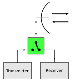
In radar, a transmit/receive (TR) switch alternately connects the transmitter and receiver to a shared antenna. In the simplest arrangement, the switch consists of a gas-discharge tube across the input terminals of the receiver. When the transmitter is active, the resulting high voltage causes the tube to conduct, shorting together the receiver terminals to protect it, while its complementary, the anti-transmit/receive (ATR) switch, is a similar discharge tube which decouples the transmitter from the antenna while not operating, to prevent it from wasting received energy.
Circulator
Hybrid
A hybrid, such as a magic T, may be used as a duplexer by terminating the fourth port in a matched load.[2] This arrangement suffers from the disadvantage that half of the transmitter power is lost in the matched load, while thermal noise in the load is delivered to the receiver.
Orthomode transducer
Frequency domain

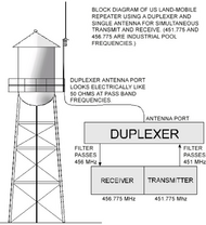
In radio communications (as opposed to radar), the transmitted and received signals can occupy different frequency bands, and so may be separated by frequency-selective filters. These are effectively a higher-performance version of a diplexer, typically with a narrow split between the two frequencies in question (typically around 2%-5% for a commercial two-way radio system).
With a duplexer the high- and low-frequency signals are traveling in opposite directions at the shared port of the duplexer.
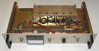
Modern duplexers often use nearby frequency bands, so the frequency separation between the two ports is also much less. For example, the transition between the uplink and downlink bands in the GSM frequency bands may be about one percent (915 MHz to 925 MHz). Significant attenuation (isolation) is needed to prevent the transmitter's output from overloading the receiver's input, so such duplexers employ multi-pole filters. Duplexers are commonly made for use on the 30-50 MHz ("low band"), 136-174 MHz ("high band"), 380-520 MHz ("UHF"), plus the 790–862 MHz ("800"), 896-960 MHz ("900") and 1215-1300 MHz ("1200") bands.
There are two predominant types of duplexer in use - "notch duplexers", which exhibit sharp notches at the "unwanted" frequencies and only pass through a narrow band of wanted frequencies and "bandpass duplexers", which have wide-pass frequency ranges and high out-of-band attenuation.
On shared-antenna sites, the bandpass duplexer variety is greatly preferred because this virtually eliminates interference between transmitters and receivers by removing out-of-band transmit emissions and considerably improving the selectivity of receivers. Most professionally engineered sites ban the use of notch duplexers and insist on bandpass duplexers for this reason.

Isolation typical >75 dB
Insertion Loss typical < 1.0 dB
Note 1: A duplexer must be designed for operation in the frequency band used by the receiver and transmitter, and must be capable of handling the output power of the transmitter.
Note 2: A duplexer must provide adequate rejection of transmitter noise occurring at the receive frequency, and must be designed to operate at, or less than, the frequency separation between the transmitter and receiver.
Note 3: A duplexer must provide sufficient isolation to prevent receiver desensitization.
Source: from Federal Standard 1037C
History
The first duplexers were invented for use on the electric telegraph and were known as duplex rather than duplexer. They were an early form of the hybrid coil. The telegraph companies were keen to have such a device since the ability to have simultaneous traffic in both directions had the potential to save the cost of thousands of miles of telegraph wire. The first of these devices was designed in 1853 by Julius Wilhelm Gintl of the Austrian State Telegraph. Gintl's design was not very successful. Further attempts were made by Carl Frischen of Hanover with an artificial line to balance the real line as well as by Siemens & Halske, who bought and modified Frischen's design. The first truly successful duplex was designed by Joseph Barker Stearns of Boston in 1872. This was further developed into the quadruplex telegraph by Thomas Edison. The device is estimated to have saved Western Union $500,000 per year in construction of new telegraph lines.[3][4]
The first duplexers for radar, sometimes referred to as Transmit/Receive Switches, were invented by Robert Morris Page and Leo C. Young of the United States Naval Research Laboratory in July 1936.[5]
References
- ↑ Rinehart, Ronald E. (1991). Radar for Meteorologists. University of North Dakota. Radar engineers have added the automatic switch (also called a duplexer) in the ... As soon as the transmitter stops sending a signal, the duplexer switches so that the receiver is now connected to the antenna.
- ↑ Sisodia; Gupta (2007). Microwaves: Introduction To Circuits,Devices And Antennas. New Delhi: New Age International. p. 4.40. ISBN 9788122413380. https://books.google.com/books?id=iEvgmwH1esgC&pg=SA4-PA40.
- ↑ Tom Standage, The Victorian Internet, ch. 11, Walker & Company, 2007 ISBN 978-0-802-71879-2.
- ↑ George Bartlett Prescott, Electricity and the Electric Telegraph, pp. 792-793, New York: D. Appleton, 1877 OCLC 999414808
- ↑ Page, Robert Morris; The Origin of Radar, Doubleday & Company, 1962, pp. 118-125
 |
