Engineering:Dynamometer car


A dynamometer car is a railroad maintenance of way car used for measuring various aspects of a locomotive's performance. Measurements include tractive effort (pulling force), power, top speed, etc.
History
The first dynamometer car was probably one built in about 1838 by the "Father of Computing" Charles Babbage.[1][2][3] Working for the Great Western Railway of Great Britain, he equipped a passenger carriage to be placed between an engine and train and record data on a continuously moving roll of paper. The recorded data included the pulling force of the engine, a plot of the path of the carriage and the vertical shake of the carriage. The work was undertaken to help support the position of the Great Western Railway in the controversy over standardizing the British track gauge.
In the United States, the Pennsylvania Railroad began using dynamometer cars in the 1860s.[4] The first modern dynamometer car in the United States was built in 1874 by P. H. Dudley for the New York Central Railroad.
The early cars used a system of springs and mechanical linkages to effectively use the front coupler on the car as a scale and directly measure the force on the coupler. The car would also have a means to measure the speed of the train. Later versions used a hydraulic cylinder and line to transmit the force to the recording device.
Modern dynamometer cars typically use electronic solid state measuring devices and instrumentation such as strain gauges.
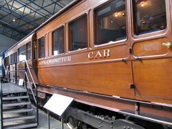
A LNER dynamometer car was used to record No 4468 Mallard's speed record in 1938, and has been preserved at the National Railway Museum in York, England. This was also used for British Railways 1948 Locomotive Exchange Trials along with two other dynamometer cars, both of which have also survived into preservation.
A car originally belonging to the Chicago, Burlington and Quincy Railroad, is preserved at the National Railroad Museum located in Green Bay, Wisconsin. A car built for the Chicago, Milwaukee, St. Paul and Pacific Railroad is preserved at the Illinois Railway Museum.[5]
Usage
While the principal purpose of the dynamometer car was to measure the power output of locomotive, other data were typically collected, such as smoke box data, throttle settings and valve cut offs, fuel burn rates, and water usage to determine the overall performance and efficiency of the locomotive.
Data would typically be recorded on time-indexed continuous paper recording rolls for the pull and velocity. Power would later be manually calculated from these data on early cars. Some later cars were equipped with a mechanical integrator to directly record the power.[4]
A separate use for the car was to test a particular rail route to rate it for tonnage based on a run with a dynamometer car and recording the effect of the grades and curvature on the capacity and resulting power requirements for that line.[4]
Power calculations
The operating principle of the dynamometer car is based on the basic equation for power being equal to force times distance over time.
This equation can be reduced to power equals force times velocity:
In other words, the instantaneous power output of the locomotive can be calculated by measuring the pull on the coupler and multiplying by the current speed.
Converting to horse power gives:
References
- ↑ "XXV. Railways". Passages from the life of a philosopher. Longman, Green, Longman, Roberts and Green. 1994 (published 1864). pp. 328–334. https://archive.org/stream/passagesfromlif00babbgoog#page/n334/mode/1up.
- ↑ M. V. Wilkes (2002). "Charles Babbage and his world". Notes and Records of the Royal Society 56 (3): 353–365. doi:10.1098/rsnr.2002.0188.
- ↑ *K. K. Schwarz (2002). "Faraday and Babbage". Notes and Records of the Royal Society 56 (3): 367–381. doi:10.1098/rsnr.2002.0189.
- ↑ 4.0 4.1 4.2 Hay, William W (1982). Railread Engineering. John Wiley & Sons. pp. 213–214. ISBN 0471364002. https://books.google.com/books?id=ygKio-Ks0doC&q=LOCOMOTIVE+dynamometer&pg=PA213. Retrieved 17 October 2014.
- ↑ "Chicago Milwaukee St. Paul & Pacific (Milwaukee Road) X5000". Illinois Railway Museum. https://www.irm.org/cgi-bin/rsearch.cgi?swork=Chicago+Milwaukee+St.+Paul+&+Pacific+(Milwaukee+Road)=X5000.
External links
- Testing a Locomotive — Comprehensive details of how a dynamometer car is used for performance testing
- Rail Training & Test Cars photos of some prototype cars.
- Carriages of LNWR: 6-wheeled Dynamometer Car
- Laboratory on Wheels Details (including publicity article from February 1951) of the Victorian & South Australian Railways' dynamometer car
- Esoteric Test Equipment
- Norfolk & Western dynamometer car drawings
 |
