Engineering:Keyboard matrix circuit
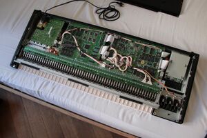
A keyboard matrix circuit is a design used in most electronic musical keyboards and computer keyboards in which the key switches are connected by a grid of wires, similar to a diode matrix. For example, 16 wires arranged in 8 rows and 8 columns can connect 64 keys—sufficient for a full five octaves of range (61 notes). By scanning these crossings, a keyboard controller can determine which keys are currently pressed.[1]
Description
Without a matrix circuit, a 61-key keyboard for a digital piano or a computer keyboard might require 62 wires to connect (one for each key, and a ground)—an awkwardly thick bundle of wiring. With a matrix circuit, any of 61 keys can be determined with only 16 wires. This is drawn schematically as a matrix of 8 columns and 8 rows of wires, with a switch at every intersection. The keyboard controller scans the columns. If a key has been pressed, the controller scans the rows, determines the row-column combination at which a key has been pressed, and generates the code corresponding to that key. This process occurs so quickly that the user is unaware of any delay.[1]
There are at least two limitations with this system. The first is that it provides only a crude binary on/off signal for each key. Better electronic musical keyboards employ two sets of switches for each key that are slightly offset. By determining the timing between the activation of the first and second switches, the velocity of a key press can be determined—greatly improving the performance dynamic of a keyboard.
The second is that instruments with a matrix circuit can only play in a monophonic fashion without the addition of a diode for each key crossing.[2] The diode prevents unwanted notes ("phantom keys") from being triggered, or intended notes from being masked ("phantom key blocking").[1]
Monophonic instruments and most low-cost computer keyboards reduce costs by leaving out most or all of those diodes. To avoid "phantom keys", the keyboard controller in modern low-cost computer keyboards will ignore further key presses once two keys (other than modifier keys) have been pressed, which is known as key jamming or ghosting.
In addition to musical keyboards and regular computer keyboards, the matrix circuit approach is also used in keypads (such as for calculators) and pinball machines.[3][4]
Often in pocket calculators the multiplexed digit drive lines would be used to scan the keyboard as well, providing further savings.[5]
See also
- Charlieplexing
- Crossbar switch
- Diode matrix
- Polyphony (instrument)
References
- ↑ 1.0 1.1 1.2 Dave Dribin. "Keyboard Matrix Help". 2000.
- ↑ Jim Cairns, "Keyboard Encoders" jimspage.co.nz
- ↑ Jeff Tyson and Tracy V. Wilson. "How Computer Keyboards Work"
- ↑ "Understanding the Switch Matrix". http://webpages.charter.net/coinopcauldron/swarticle.html.
- ↑ Stan D’Souza. "Microchip AN529: Multiplexing LED Drive and a 4x4 Keypad Sampling". 1997.
 |


