Engineering:Magnetically controlled shunt reactor
This article has multiple issues. Please help improve it or discuss these issues on the talk page. (Learn how and when to remove these template messages)
(Learn how and when to remove this template message)No issues specified. Please specify issues, or remove this template. |
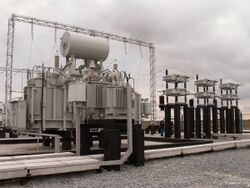
In electrical engineering, a magnetically-controlled shunt reactor (MCSR, CSR) represents electrotechnical equipment purposed for compensation of reactive power and stabilization of voltage level in high voltage (HV) electric networks rated for voltage classes 36 – 750 kV. MCSR is a shunt-type static device with smooth regulation by means of inductive reactance.
History
In 2002, The first Controlled Shunt Reactor (CSR) was developed by Bharat Heavy Electricals Limited. The first such device was commissioned at Power Grid's 400 kV Itarsi substation in Madhya Pradesh.[1]
Purpose
Magnetically-controlled shunt reactors are intended for automatic control over reactive power and stabilization of voltage levels; these ensure the following:

- Elimination of daily and seasonal voltage variations in the power network;[2]
- Improvement of electric power quality;
- Optimization and automation of power network operating modes;
- Reduction of electric power losses within its transmission and distribution;
- Improvement of power system stability;
- Enhancement of the conditions of operation in tens of times and prolongation of service life of the electric equipment by virtue of dynamic shortcut of switchings of uncontrolled devices for reactive power compensation as well as limitation of operation of less reliable devices – OLTC, transformers and autotransformers
- Increasing of transmission line throughput performance and provision of reliable automatic control over voltage levels at power overflows close to limit values as referred to static stability;
- Avoiding of voltage collapse effect at emergency situations in the power network (for example, emergency trip of load, generator, transmission line, etc.;
- Assurance of operating conditions for power plant generators in such reaction power generation range which assist to the most favorable operating modes.
Field of application
On the assumption of tasks to be solved by MCSRs, as well as with consideration of existing experience of their operation, application field of controlled reactors covers (but not limited) the following areas of the power networks:
- networks with abrupt-changed load curves;
- networks with worn-out switching and transformer equipment been used frequently for regulation of voltage levels;
- networks made using long-length transits, which tend to frequent variation of power flows’ value and/or direction;
- networks for power supply of the consumers with enhanced demand of voltage stability;
- networks with increased losses;
- networks having operating mode, which does not allow to provide permissible load of the generators as referred to reactive power.
Ample opportunities of MCSRs ensure expediency of their application for different voltage classes. Furthermore, expected effect could be shown up both at the level of local area consumer’s grids, and at solving the primary tasks of the national power system as a whole.
In the context of building-up of the market relations in the electric energy sector and increase of investments for development of power networks, MCSRs offer the complete series of considerable benefits for all economic entities:
- at the level of feeding and distribution electric networks, MCSRs ensure significant reduction of electric power losses and increase of profits of system operator and distribution companies, respectively;
- as referred to electric power consumers, MCSRs are installed for the purpose of reduction of the charges to be paid for consumed reactive power (maintaining of cos (ɸ)), ensuring the required voltage quality at the point of final customers, as well as in the capacity of required measures for connection of new capacities to the network.
Operating principle
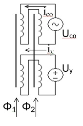
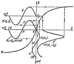
A magnetically-controlled shunt reactor is a transformer-type device which additionally provides functions of semiconducting key apparatus; this is ensured by means of reactor magnetic system operation in the domain of deep saturation. The basing principle allowed optimal employment of existing designs both in transformer production industry, and in the field of power electronics. Magnetic system of MCSR single phase includes two cores with windings, vertical and horizontal yokes. Control windings with opposite connection and power windings with series (accordant) connection are arranged on CST magnetic system cores. MCSR magnetic system cores are free from nonmagnetic gaps, and owing to this effect in case of the reactor connection to the network it will be in no-load condition. Herewith, the value of reactive power consumed from the grid will not exceed 3% of nominal magnitude. To increase reactor load as for reactive power, its operating range should be offset to non-linear area of hysteresis characteristic; and this is achieved for the account of additional biasing of magnetic system. At connection of regulated dc voltage source to the control windings, increase of the bias flux is ensured.

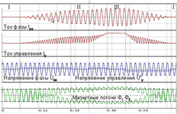
Due to the fact that ac flow of power winding is superimposed on the bias flux, the net flux is offset to the saturation domain of magnetic system cores. Respectively, saturation of the cores is resulted in occurrence of current in the power winding. In case of energy input to or output from the control circuit, the transient process of increase or decrease of network current and, respectively, of reactive power consumed by reactor is ensured.

Reactor power winding current is regulated according to proportional control mode, when control angle of rectified current source thyristors is changed according to proportional mode depending on mismatching between the prescribed voltage setting and the voltage at the point of reactor connection. In case of necessity to implement the rapid transfer of the reactor from one quasi-steady-state mode to another one, the scheme of overexcitation/underexcitation is realized. In such case, time to gain full power starting from no-load condition is reduced up to 0,3 s. Constructively, it is possible to ensure every speed of the reactor power variation. However, based on practical experience of MCSR application, the optimal balance between the reactor operating speed and capacity of biasing system has been determined: speed of power increase/relief within 0,3 – 1,0 s, capacity of biasing system – 1 – 2% of the reactor rated capacity.

Depending upon desired requirements, MCSR is adjusted in such a way that would be possible to realize either voltage level stabilization, or consumed reactive power value, or consumed current magnitude. Controlled reactors, same as their non-controlled analogues, are subdivided into bus reactors and line reactors. Based on this principle, MCSR design would be completed with additional element which ensures pre-biasing of electromagnetic part and subsequent inertialess energizing of the reactor (with power increase time less than one cycle of power frequency). Similar to all transformer equipment, MCSR is able to withstand long-term overload up to 120 – 130% as well as should-term overload up to 200%. Moreover, considering the additional measures and the control algorithms, MCSR realizes all functions of uncontrolled shunt reactor including ability to operate within the interval of single-phase automatic reclosing.
Bibliography
- Electric reactors controlled by biasing. / Collected works edited by Doctor of Technical Science, Professor A.M. Bryantsev. — M.: “Znak”. 264 p. Il., 2004. —ISBN 5-87789-054-9.
- Shunt reactors controlled by biasing / Monograph edited by Doctor of Technical Science, Professor G.A. Yevdokunin. — Publishing House “Rodnaya Ladoga”. 280 p., 2013. —ISBN 978-5-905657-07-8. .
- Reactive power static compensator based on CSR as mandatory facility for Energy Efficiency in the power industry / D.V. Kondratenko, A.G. Dolgopolov, T.A. Shibayeva, A.V. Vishtibeyev. — Electro magazin, №2., 2009..
- Overhead transmission lines equipped with CSR. Single-phase automatic reclosing. / A.G. Dolgopolov, D.V. Kondratenko, M.V. Dmitriyev, G.A. Yevdokunin, E.B. Sheskin. — Electro magazin, №4., 2012..
- Experience of application of line controlled shunt reactors. Possible problems and solution approaches. / K.V. Aristov, A.G. Dolgopolov, D.V. Kondratenko, Y.V. Sokolov. — Electro magazin, №4., 2012
References
- ↑ Correspondent, Our (21 November 2002). "Bhel develops device to reduce T&D losses". The Times of India. https://timesofindia.indiatimes.com/business/india-business/bhel-develops-device-to-reduce-td-losses/articleshow/28959774.cms.
- ↑ Russia Grids builds new power lines between Krasnoyarsk Krai and Irkutsk Oblast
 |
