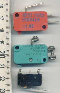
Engineering:Miniature snap-action switch

A miniature snap-action switch, also trademarked and frequently known as a micro switch or microswitch, is an electric switch that is actuated by very little physical force, through the use of a tipping-point mechanism, sometimes called an "over-center" mechanism.
The defining feature of micro switches is that a relatively small movement at the actuator button produces a relatively large movement at the electrical contacts, which occurs at high speed (regardless of the speed of actuation). Switching happens reliably at specific and repeatable positions of the actuator, which is not necessarily true of other mechanisms. Most successful designs also exhibit hysteresis, meaning that a small reversal of the actuator is insufficient to reverse the contacts; there must be a significant movement in the opposite direction. Both of these characteristics help to achieve a clean and reliable interruption to the switched circuit.
They are very common due to their low cost but high durability, greater than 1 million cycles, and up to 10 million cycles for heavy-duty models. This durability is a natural consequence of the design.
History
The first micro switch was invented by Phillip Kenneth McGall in 1932 in Freeport, Illinois, under patent US1,960,020.[1] McGall was an employee of the Burgess Battery Company at the time. In 1937 W.B. Schulte,[2] McGall's employer, started the company MICRO SWITCH. The company and the Micro Switch trademark have been owned by Honeywell Sensing and Control since 1950.[3] The name has become a generic trademark for any snap-action switch. Companies other than Honeywell now manufacture miniature snap-action switches.
Construction and operation

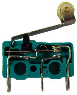
In one type of microswitch,[4] internally there are two conductive springs. A long flat spring is hinged at one end of the switch (the left, in the photograph) and has electrical contacts on the other. A small curved spring, preloaded (i.e., compressed during assembly) so it attempts to extend itself (at the top, just right of center in the photo), is connected between the flat spring near the contacts and a fulcrum near the midpoint of the flat spring. An actuator nub presses on the flat spring near its hinge point.
Because the flat spring is anchored and strong in tension the curved spring cannot move it to the right. The curved spring presses, or pulls, the flat spring upward, that is away, from the anchor point. Owing to the geometry, the upward force is proportional to the displacement which decreases as the flat spring moves downward. (Actually, the force is proportional to the sine of the angle, which is approximately proportional to the angle for small angles.)
As the actuator depresses it flexes the flat spring while the curved spring keeps the electrical contacts touching. When the flat spring is flexed enough it will provide sufficient force to compress the curved spring and the contacts will begin to move.
As the flat spring moves downward the upward force of the curved spring reduces causing the motion to accelerate even in the absence of further movement of the actuator until the flat spring impacts the normally-open contact. Even though the flat spring unflexes as it moves downward, the switch is designed so the net effect is acceleration. This "over-center" action produces a very distinctive clicking sound and a very crisp feel.
In the actuated position the curved spring provides some upward force. If the actuator is released this will move the flat spring upward. As the flat spring moves, the force from the curved spring increases. This results in acceleration until the normally-closed contacts are hit. Just as in the downward direction, the switch is designed so that the curved spring is strong enough to move the contacts, even if the flat spring must flex, because the actuator does not move during the changeover.
Applications
Microswitches have two main areas of application:
- Firstly, they are used when a low operating force with a clearly defined action is needed.
- Secondly, they are used when long-term reliability is needed. This is a result of the internal mechanism and the independence of the closing force on the switch contacts from the operating force. Switch reliability is largely a question of the contact force: a force that is reliably adequate, but never excessive, encourages long life.
Common applications of micro switches include the door interlock on a microwave oven, leveling and safety switches in elevators, vending machines, arcade buttons, and to detect paper jams or other faults in photocopiers. Microswitches are commonly used in tamper switches on gate valves on fire sprinkler systems and other water pipe systems, where it is necessary to know if a valve has been opened or shut.
Micro switches are very widely used; among their applications are appliances, machinery, industrial controls, vehicles, convertible tops, and many other places for control of electrical circuits. They are usually rated to carry current in control circuits only, although some switches can be directly used to control small motors, solenoids, lamps, or other devices. Special low-force versions can sense coins in vending machines, or with a vane attached, airflow. Microswitches may be directly operated by a mechanism, or maybe packaged as part of a pressure, flow, or temperature switch, operated by a sensing mechanism such as a Bourdon tube. In these latter applications, the repeatability of the actuator position when switching happens is essential for long-term accuracy. A motor-driven cam (usually relatively slow-speed) and one or more micro switches form a timer mechanism. The snap-switch mechanism can be enclosed in a metal housing including actuating levers, plungers, or rollers, forming a limit switch useful for control of machine tools or electrically-driven machinery.
See also
References
- ↑ "US1960020A". Google Patents. https://patents.google.com/patent/US1960020A/en.
- ↑ Shouer, Dick (1 March 2015). Honeywell History. Honeywell.
- ↑ "MICRO SWITCH Timeline - 1950s". http://sensing.honeywell.com/1/4/6/5/6/1/index1.shtml.
- ↑ Piter, Tiago. "Micro switch". https://www.unionwells.com/micro-switch.html.
External links
 |
