Engineering:Modular Engine Management System
 MEMS 1.6 units, one with its cover removed | |
| Manufacturer | Rover Group / Motorola |
|---|---|
| Type | Electronic automobile engine management |
| Release date | 1989 |
The Modular Engine Management System, or MEMS, is an electronic control system used on engines in passenger cars built by Rover Group in the 1990s. As its name implies, it was adaptable for a variety of engine management demands, including electronically controlled carburetion as well as single- and multi-point fuel injection (both with and without electronic ignition control). The abbreviations "SPi" and "MPi" refer to the single-point and multi-point injection configurations, respectively.[1]
In 1985, Rover Group made the decision to develop a new electronic engine management system in-house, and from its inception, the system was intended to be flexible enough for use with future engine designs. It was also intended to improve quality and reliability and to consume less power and occupy less underbonnet space than previous engine management systems.[2] The system first became available in 1989, when it was fitted to the Austin Montego 2.0L. Over the next seven years, the system appeared on cars across Rover's model lineup, including the Mk VI and Mk VII Mini and the MG F / MG TF. It was also paired with Rover engines used by other marques, such as the Lotus Elise and several Caterham models using the Rover K-series engine.[3]
Hardware
The ECU design was a joint venture between Rover and Motorola Automotive and Industrial Electronics Group (AIEG), who were responsible for the ECU manufacturing. The software run on the ECU was designed and written by Rover Group engineers. The "Modular" characteristic of the ECU was represented in the hardware design, which featured a common core with multiple optional add-on modules. In 1990, these modular features included the following:[2]
- Base programmed ignition
- Single fuel injector
- Second fuel injector
- Batch-fired (bank) fuel injectors
- Automatic transmission control
- Pulse air
- Exhaust gas recirculation
- Purge valve control
- Knock sensing
- Air conditioning control
- Oxygen sensor(s)
The processor in the ECU is an Intel 8096 running at 12 MHz and featuring 8KB of on-chip ROM for storage of code and data and 232 bytes of general-purpose RAM. The main connector is a 36-pin TE Connectivity 344108 ("Econoseal"), and its mating connector (used in the wiring harness) is a TE Connectivity 344111. On earlier versions of the system, a MAP sensor was internal to the ECU, requiring that an inlet manifold vacuum line be run to the ECU enclosure. In MEMS 1.6 and 1.9, this MAP sensor is the Motorola 5141550T02,[4] and the vacuum line feeding it passes through a vapor trap to prevent admission of fuel vapor into the ECU.[5]
An analogous system for engines with a carburettor was developed at the same time as MEMS. This system was known as "ERIC", which stands for "Electronically Regulated Ignition and Carburetion".[1] The development of the MEMS and ERIC systems became the first in-house units for ignition and fuel-control, areas which had previously been undertaken by Lucas Engine Management Systems, a division of Lucas Industries. While the development of MEMS and ERIC occurred at the same time, there was no commonality between the two systems - while MEMS used an Intel micro-controller, the ERIC system used the Motorola 68HC11 device; the development of MEMS used a PC based toolset, while that of ERIC used a Unix based toolset; the two teams working on MEMS and ERIC were totally independent.[citation needed]
Function
Like other electronic engine management systems, MEMS reads data from a number of sensors and computes an appropriate fueling rate and ignition advance/retard. The ECU samples engine speed, manifold absolute pressure, coolant temperature, intake air temperature, throttle position, and battery voltage. Base values for the fueling and ignition timing are each retrieved from a three-dimensional map, and certain sensor values are applied as correction factors, for example, to enrich fueling during wide-throttle acceleration or on cold startup. The MEMS firmware also features a limp-home capability (referred to in the literature as "limited operating strategy") that will substitute a nominal value for any non-operative sensor.[1]
Crankshaft position and speed are determined by input signals generated by poles in a magnetic reluctance disc. The system may be run in either open-loop or closed-loop mode (with the latter requiring a lambda sensor). Additional features include an engine speed limiter, overrun fuel cut-off, startup fuel enrichment (both during cranking and after startup), and fueling compensation for battery voltage. Some operating parameters are learned by the ECU over time, such as the optimal IAC valve position for a stable idle. This accommodates slight differences in engine wear and tune between different engines.[6]
Among the different revisions of MEMS were the following:
- 1.2: First version to enter production. Not designed for use in vehicles with catalytic converters. ECU has single 36-pin connector.
- 1.3: Designed with capability to control emissions-related equipment. ECU has two connectors (one 36-pin and one 18-pin).
- 1.6: Finned aluminum enclosure normally with single 36-pin connector, some have a 36-pin and 18-pin connector.
- 1.9 Introduced in mid-1994, version 1.9 of the system uses a redesigned mechanism for idle air control and supports multipoint injection.
- 2J: Supports sequential injection (with a fallback to batch-fired injectors in the event of a cam position sensor failure.) Also supports variable valve timing control in the form of Rover VVC.[7]
- 3: Supports EOBD3 (European On Board Diagnostics version 3)[7]
Diagnostics
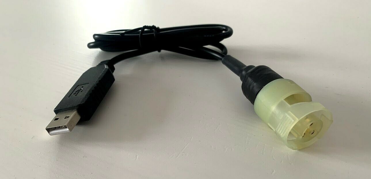
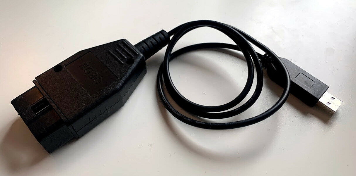
Because it was designed before industry-wide on-board diagnostics were standardized, early versions of MEMS use a proprietary diagnostics protocol and signaling scheme. This protocol is known as ROSCO, which is an abbreviation for Rover Service Communications.[8] On earlier cars, the diagnostic port used a circular three-pin connector (type 172202 manufactured by TE Connectivity), where later cars switched to the standardized 16-pin ISO J1962 connector type.
When the system detects a fault, a corresponding fault code is stored in the ECU's non-volatile memory. Fault codes may only be cleared by commanding the ECU via the diagnostic port. Testing of MEMS equipped cars was originally possible with the "COBEST", "Microcheck", and "Microtune" test equipment provided to Rover dealerships and service centers.[6][9] The Rover TestBook system later became available to provide similar functionality as well.[2]
There are now various open and closed source applications for PC and mobile phones in order to interact with these ECUs, rather than having to purchase an old Testbook tool.
References
- ↑ 1.0 1.1 1.2 White, Charles (July 1997). Automotive Engine Management and Fuel Injection Manual. Haynes Techbooks. ISBN 978-1859603444.
- ↑ 2.0 2.1 2.2 Crabb, D.; Duncan, H.M.; Hiljemark, S.L.; Kershaw, T.J. (14–18 May 1990). "MEMS (Modular Engine Management System)" (PDF). Twenty-second International Symposium on Automotive Technology and Automation. Florence, Italy: Joint Publications Research Service (published 26 September 1990). pp. 127–134. https://ssims.co.uk/Downloads/MEMS%20Paper.pdf. Retrieved 2014-01-27.
- ↑ Rees, Chris (2013-08-01). The Magnificent 7. Haynes Publishing. ISBN 978-0857333919.
- ↑ "MGF MEMS 1.9 ECU". https://www.mgfcar.de/mems1.9/index.htm.
- ↑ "Diagnosing and fixing vacuum leaks". https://memsfcr.co.uk/2023/01/31/diagnosing-and-fixing-vacuum-leaks/.
- ↑ 6.0 6.1 "T16 MEMS Electrics". http://www.newpcworld.com/cars/rover/technical_manuals/t16_mems_electrics.pdf.
- ↑ 7.0 7.1 Parker, Roger (2013-01-01). MGF and TF Restoration Manual. The Crowood Press UK. ISBN 978-1847974006.
- ↑ Williams, Mike (April 1990). "Automotive electronics in Europe -- the real issue is cost". Research Newsletter (Dataquest) (1990–8). http://archive.computerhistory.org/resources/access/text/2013/04/102723414-05-01-acc.pdf. Retrieved 2015-10-12.
- ↑ Rover Product Training College (1989). Rover MEMS Service (Videotape). Rover Service TV Unit. Retrieved 2014-01-28.
External links
- MGF TF MEMS ECU Motorola (MEMS 1.9)
- Rover MEMS diagnostic protocol
- 3-pin diagnostic cable
- 16-pin diagnostic cable
 |  |
