Engineering:Round-topped boiler
.jpg)

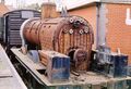
A round-topped boiler is a type of boiler used for some designs of steam locomotive and portable engine. It was an early form of locomotive boiler, although continuing to be used for new locomotives through to the end of steam locomotive manufacture in the 1960s.
Firebox
They use the early form of firebox, where the outer wrapper of the firebox is a semi-circular continuation of the cylindrical boiler barrel. They are relatively simple in shape and manufacture, but their design and service is complicated by the difference in shape between the outer and the flat-topped inner wrapper of the firebox. This requires complex staying to support it.
The first boilers of this form had raised fireboxes that were considerably larger, particularly higher, than the boiler barrel. In the extreme case, this gave rise to the haycock boiler, where the firebox was raised into a vaulted dome. In most cases though, the firebox was merely larger by the width of the internal iron framing section. Around 1850, at the instigation of Crampton,[1] the firebox adopted the flush-topped firebox casing, where it was of the same diameter as the boiler barrel and joined to it by riveted lap strips.
The early boiler fireboxes had flat parallel sides (see figure 1). As locomotives grew in power their boilers expanded in diameter, but the width of the firebox grate was still constrained by the need to fit between the locomotive frames, which were themselves constrained by the gauge between the wheels. This led to the development of the "waisted" form (see figure 2), where a narrow firebox flared upwards and outwards to meet the boiler barrel. Staying of these firebox side walls could still use simple short rod stays, although these were progressively tilted in the middle of the firebox, so as to remain perpendicular to the sheets.
Because the shape of the firebox follows the shape of the boiler barrel, they are used for saddle tank locomotives. The Hunslet Austerity, the last production steam locomotives to be constructed in the UK, used this form.[2]
Staying
The upper crown sheet of the inner firebox is, as with most locomotive boilers, approximately flat and horizontal, so as to maintain a constant depth of water over this hottest part of the firebox. This flat surface, with steam pressure on its upper side, requires stays to support it. As it is not a constant distance from the boiler barrel, unlike the firebox sides, this staying is difficult to arrange.
Girder stays
Early examples soon used girder stays to support the inner firebox crown. These are iron girders spanning the length or width, on the outside of the inner firebox (i.e. in the water space). The crown sheet is bolted to these. The force on the ends of the girder stays is supported by the ends or sides of the inner firebox. The upper part of the boiler barrel is unconnected to the firebox. This has the advantage that a large hole may be cut in the boiler directly above the firebox, to mount the steam dome.
Rod and sling stays
.jpg)
Larger boilers could not support their firebox crowns entirely on the inner firebox and required a means to support it from the boiler barrel. As this is also forced outwards by the steam pressure, the total force could be shared between many small stays. Each stay carried enough force on each end to balance itself, avoiding the large bending forces at the ends of the girder stays
Thermal expansion was a problem for these long rod stays, both in their expansion tending to elongate them and reduce their staying effect . Also as the inner firebox expanded in length, this would bend the stays forwards. Where a long firebox was stayed, the forward rod stays were replaced with sling stays, a rod stay with a hinge at the upper end, allowing it to move forwards with the firebox.
These stays were also placed in the most active part of the boiler, where corrosion was at its worst. Careful inspection and periodic replacement of them was needed, to avoid the risk of a boiler explosion.
The main difficulty of rod stays was that it required a large number of rod stays, each of which was placed at a different angle to its neighbour. The complexity of this rod staying was what drove Alfred Belpaire to develop his Belpaire firebox. This used a more complicated squared-off outer firebox, which was more difficult to manufacture, but could now use simple short rod stays throughout, as for the firebox sides.
Examples
Locomotive designs fitted with round-topped boilers:
-
 NER Class C1 876 at Beamish Museum in 2001
 -
 Same locomotive, 876, dismantled for overhaul in 2008
.png)

See also
- Belpaire firebox
- Wootten firebox
References
- ↑ Ahrons, E. L. (1927). The British Steam Railway Locomotive 1825-1925. Amen Corner, London: Locomotive Publishing Co.. pp. 86–87.
- ↑ Hunslet Engine Company (2006). Spare Parts List, Austerity Locomotive. Camden Miniature Steam Services. pp. 10–11. ISBN 978-0-9547131-4-0.
- ↑ Mechanical Transport. Army Service Corps Training. HMSO. 1911.
- ↑ J.F. Gairns (1923). Railways for All. Ward Lock. pp. facing p.49.
 |  |
