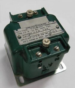
Engineering:Voltage transformer

Voltage transformers (VT), also called potential transformers (PT), are a parallel-connected type of instrument transformer. They are designed to present a negligible load to the supply being measured and have an accurate voltage ratio and phase relationship to enable accurate secondary connected metering.
Ratio
The PT is typically described by its voltage ratio from primary to secondary. A 600:120 PT will provide an output voltage of 120 volts when 600 volts are impressed across its primary winding. Standard secondary voltage ratings are 120 volts and 70 volts, compatible with standard measuring instruments.
Burden and accuracy
Burden and accuracy are usually stated as a combined parameter due to being dependent on each other. Metering style PTs are designed with smaller cores and VA capacities than power transformers. This causes metering PTs to saturate at lower secondary voltage outputs saving sensitive connected metering devices from damaging large voltage spikes found in grid disturbances. A small PT (see nameplate in photo) with a rating of 0.3W, 0.6X would indicate with up to W load (12.5 watts[1] ) of secondary burden the secondary current will be within a 0.3 percent error parallelogram on an accuracy diagram incorporating both phase angle and ratio errors. The same technique applies for the X load (25 watts) rating except inside a 0.6% accuracy parallelogram.[2]
Markings
Transformer winding primary (usually high-voltage) connecting wires are of many types. They may be labeled as H1, H2 (sometimes H0 if it is internally designed to be grounded) and X1, X2 and sometimes an X3 tap may be present. Sometimes a second isolated winding (Y1, Y2, Y3) (and third (Z1, Z2, Z3) may also be available on the same voltage transformer. The primary may be connected phase to ground or phase to phase. The secondary is usually grounded on one terminal to avoid capacitive induction from damaging low-voltage equipment and for human safety.
Types of voltage transformers
There are three primary types of potential transformers (PT): electromagnetic, capacitor, and optical. The electromagnetic potential transformer is a wire-wound transformer. The capacitor voltage transformer (CVT) uses a capacitance potential divider and is used at higher voltages due to a lower cost than an electromagnetic PT. An optical voltage transformer exploits the Faraday effect, rotating polarized light, in optical materials.[3]

A capacitive voltage transformer (CVT), also known as capacitor-coupled voltage transformer (CCVT), is a transformer used in power systems to step down extra high voltage signals and provide a low voltage signal to the actual VT (voltage transformer) used for operating metering/protective relays.
In its most basic form, the device consists of three parts: two capacitors across which the transmission line signal is split, an inductive element to tune the device to the line frequency, and a voltage transformer to isolate and further step down the voltage for metering devices or protective relay.
The tuning of the divider to the line frequency makes the overall division ratio less sensitive to changes in the burden of the connected metering or protection devices.[4] The device has at least four terminals: a terminal for connection to the high voltage signal, a ground terminal, and two secondary terminals which connect to the instrumentation or protective relay.
Capacitor C1 is often constructed as a stack of smaller capacitors connected in series. This provides a large voltage drop across C1 and a relatively small voltage drop across C2. As the majority of the voltage drop is on C1, this reduces the required insulation level of the voltage transformer. This makes CVTs more economical than the wound voltage transformers under high voltage (over 100 kV), as the latter one requires more winding and materials.
The CVT is also useful in communication systems. CVTs in combination with wave traps are used for filtering high-frequency communication signals from power frequency.[5] This forms a carrier communication network throughout the transmission network, to communicate between substations. The CVT is installed at a point after Lightning Arrester and before Wave trap.
References
- ↑ "PS-E-15 — Provisional Specifications for Approval of Electronic Voltage Transformers". Measurement Canada. http://www.ic.gc.ca/eic/site/mc-mc.nsf/eng/lm00148.html#Section6.2.
- ↑ "PS-E-15 — Provisional Specifications for Approval of Electronic Voltage Transformers". Measurement Canada. http://www.ic.gc.ca/eic/site/mc-mc.nsf/eng/lm00148.html#Section9.1.
- ↑ Network Protection & Automation anshu, AREVA 2002
- ↑ T. Davies Protection of industrial power systems second edition, Butterworth-Heinemann, 1996 ISBN:0-7506-2662-3 page 55
- ↑ Stanley H. Horowitz, Arun G. Phadke Power system relaying third edition, John Wiley and Sons, 2008 ISBN:0-470-05712-2 pages 64–65
 |

