Engineering:Wheeler Incremental Inductance Rule
The incremental inductance rule, attributed to Harold Alden Wheeler[1] by Gupta[2]:101 and others[3]:80 is a formula used to compute skin effect resistance and internal inductance in parallel transmission lines when the frequency is high enough that the skin effect is fully developed. Wheeler's concept is that the internal inductance of a conductor is the difference between the computed external inductance and the external inductance computed with all the conductive surfaces receded by one half of the skin depth.
Linternal = Lexternal(conductors receded) - Lexternal(conductors not receded).
Skin effect resistance is assumed to be equal to the reactance of the internal inductance.
Rskin = ωLinternal.
Gupta[2]:67 gives a general equation with partial derivatives replacing the difference of inductance.
- [math]\displaystyle{ L_{int}= \sum_{m} \ \frac {\mu_m} {\mu_0} \frac {\partial L} {\partial n_m} \frac {\delta_m} {2} }[/math]
- [math]\displaystyle{ R_{skin} = \sum_{m} \ \frac {R_{sm}} {\mu_0} \frac {\partial L} {\partial n_m} = \omega L_{int} }[/math]
- where
- [math]\displaystyle{ \frac {\partial L} {\partial n_m} }[/math] is taken to mean the differential change in inductance as surface m is receded in the nm direction.
- [math]\displaystyle{ R_{sm} = \frac {\omega \mu_m \delta_m} {2} }[/math] is the surface resistivity of surface m.
- [math]\displaystyle{ \mu_m = }[/math] magnetic permeability of conductive material at surface m.
- [math]\displaystyle{ \delta_m = }[/math] skin depth of conductive material at surface m.
- [math]\displaystyle{ n_m = }[/math] unit normal vector at surface m.
- where
Wadell[4]:27 and Gupta[2]:67 state that the thickness and corner radius of the conductors should be large with respect to the skin depth. Garg[3]:80 further states that the thickness of the conductors must be at least four times the skin depth. Garg[3]:80 states that the calculation is unchanged if the dielectric is taken to be air and that [math]\displaystyle{ L = {Z_c} / {V_p} }[/math] where [math]\displaystyle{ Z_c = }[/math] the characteristic impedance and [math]\displaystyle{ V_p = }[/math] velocity of propagation = the speed of light. Paul, 2007,[5] [lower-alpha 1]:149 disputes the accuracy of [math]\displaystyle{ R_{skin} = \omega L_{int} }[/math] at very high frequency for rectangular conductors such as stripline and microstrip due to a non-uniform distribution of current on the conductor. At very high frequency, the current crowds into the corners of the conductor.
Example
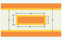
In the top figure, if
- [math]\displaystyle{ L_0 }[/math] is the inductance and [math]\displaystyle{ Z_0 }[/math] is the characteristic impedance using the dimensions [math]\displaystyle{ \mathrm{H}_0, \mathrm{W}_0 }[/math], and [math]\displaystyle{ \mathrm{T}_0 }[/math],
and
- [math]\displaystyle{ L_1 }[/math] is the inductance and [math]\displaystyle{ Z_1 }[/math] is the characteristic impedance using the dimensions [math]\displaystyle{ \mathrm{H}_1, \mathrm{W}_1 }[/math], and [math]\displaystyle{ \mathrm{T}_1 }[/math]
then the internal inductance is
- [math]\displaystyle{ L_{internal} = ( L_1 - L_0 ) = ( Z_1 - Z_0 ) / V_p }[/math] where [math]\displaystyle{ V_p }[/math] is the velocity of propagation in the dielectric.
and the skin effect resistance is
- [math]\displaystyle{ R_{skin} = \omega ( L_1 - L_0 ) }[/math]
Notes
References
- ↑ "Formulas for the Skin Effect". Proc. IRE 30 (4): 412–424. September 1942. doi:10.1109/JRPROC.1942.232015.
- ↑ 2.0 2.1 2.2 Gupta, K. C.; Garg, Ramesh; Bahl, I. J. (1979), Microstrip Lines and Slotlines, Artech House, ISBN 0-89006-074-6
- ↑ 3.0 3.1 3.2 Garg, Ramesh; Bahl, Inder; Bozzi, Maurizio (2013), Microstrip Lines and Slotlines (3 ed.), Artech House, ISBN 978-1-60807-535-5
- ↑ Wadell, Brian C. (1991), Transmission Line Design Handbook, Artech House, ISBN 0-89006-436-9
- ↑ 5.0 5.1 Paul, Clayton R. (2007), Analysis of Multiconductor Transmission Lines, Wiley, http://read.pudn.com/downloads740/ebook/2953214/TRANSMISSION_LINES.pdf


