Karnaugh map
The Karnaugh map (KM or K-map) is a method of simplifying Boolean algebra expressions. Maurice Karnaugh introduced it in 1953[1][2] as a refinement of Edward W. Veitch's 1952 Veitch chart,[3][4] which was a rediscovery of Allan Marquand's 1881 logical diagram[5][6] aka Marquand diagram[4] but with a focus now set on its utility for switching circuits.[4] Veitch charts are also known as Marquand–Veitch diagrams[4] or, rarely, as Svoboda charts,[7] and Karnaugh maps as Karnaugh–Veitch maps (KV maps).
The Karnaugh map reduces the need for extensive calculations by taking advantage of humans' pattern-recognition capability.[1] It also permits the rapid identification and elimination of potential race conditions.[clarification needed]
The required Boolean results are transferred from a truth table onto a two-dimensional grid where, in Karnaugh maps, the cells are ordered in Gray code,[8][4] and each cell position represents one combination of input conditions. Cells are also known as minterms, while each cell value represents the corresponding output value of the boolean function. Optimal groups of 1s or 0s are identified, which represent the terms of a canonical form of the logic in the original truth table.[9] These terms can be used to write a minimal Boolean expression representing the required logic.
Karnaugh maps are used to simplify real-world logic requirements so that they can be implemented using a minimum number of logic gates. A sum-of-products expression (SOP) can always be implemented using AND gates feeding into an OR gate, and a product-of-sums expression (POS) leads to OR gates feeding an AND gate. The POS expression gives a complement of the function (if F is the function so its complement will be F').[10] Karnaugh maps can also be used to simplify logic expressions in software design. Boolean conditions, as used for example in conditional statements, can get very complicated, which makes the code difficult to read and to maintain. Once minimised, canonical sum-of-products and product-of-sums expressions can be implemented directly using AND and OR logic operators.[11]
Example
Karnaugh maps are used to facilitate the simplification of Boolean algebra functions. For example, consider the Boolean function described by the following truth table.
| A | B | C | D | ||
|---|---|---|---|---|---|
| 0 | 0 | 0 | 0 | 0 | 0 |
| 1 | 0 | 0 | 0 | 1 | 0 |
| 2 | 0 | 0 | 1 | 0 | 0 |
| 3 | 0 | 0 | 1 | 1 | 0 |
| 4 | 0 | 1 | 0 | 0 | 0 |
| 5 | 0 | 1 | 0 | 1 | 0 |
| 6 | 0 | 1 | 1 | 0 | 1 |
| 7 | 0 | 1 | 1 | 1 | 0 |
| 8 | 1 | 0 | 0 | 0 | 1 |
| 9 | 1 | 0 | 0 | 1 | 1 |
| 10 | 1 | 0 | 1 | 0 | 1 |
| 11 | 1 | 0 | 1 | 1 | 1 |
| 12 | 1 | 1 | 0 | 0 | 1 |
| 13 | 1 | 1 | 0 | 1 | 1 |
| 14 | 1 | 1 | 1 | 0 | 1 |
| 15 | 1 | 1 | 1 | 1 | 0 |
Following are two different notations describing the same function in unsimplified Boolean algebra, using the Boolean variables A, B, C, D and their inverses.
- where are the minterms to map (i.e., rows that have output 1 in the truth table).
- where are the maxterms to map (i.e., rows that have output 0 in the truth table).
Construction
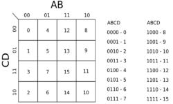
In the example above, the four input variables can be combined in 16 different ways, so the truth table has 16 rows, and the Karnaugh map has 16 positions. The Karnaugh map is therefore arranged in a 4 × 4 grid.
The row and column indices (shown across the top and down the left side of the Karnaugh map) are ordered in Gray code rather than binary numerical order. Gray code ensures that only one variable changes between each pair of adjacent cells. Each cell of the completed Karnaugh map contains a binary digit representing the function's output for that combination of inputs.
Grouping
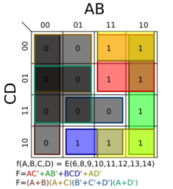
After the Karnaugh map has been constructed, it is used to find one of the simplest possible forms — a canonical form — for the information in the truth table. Adjacent 1s in the Karnaugh map represent opportunities to simplify the expression. The minterms ('minimal terms') for the final expression are found by encircling groups of 1s in the map. Minterm groups must be rectangular and must have an area that is a power of two (i.e., 1, 2, 4, 8...). Minterm rectangles should be as large as possible without containing any 0s. Groups may overlap in order to make each one larger. The optimal groupings in the example below are marked by the green, red and blue lines, and the red and green groups overlap. The red group is a 2 × 2 square, the green group is a 4 × 1 rectangle, and the overlap area is indicated in brown.
The cells are often denoted by a shorthand which describes the logical value of the inputs that the cell covers. For example, AD would mean a cell which covers the 2x2 area where A and D are true, i.e. the cells numbered 13, 9, 15, 11 in the diagram above. On the other hand, AD would mean the cells where A is true and D is false (that is, D is true).
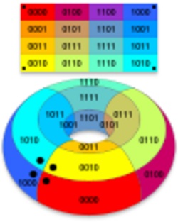
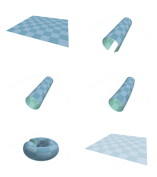
The grid is toroidally connected, which means that rectangular groups can wrap across the edges (see picture). Cells on the extreme right are actually 'adjacent' to those on the far left, in the sense that the corresponding input values only differ by one bit; similarly, so are those at the very top and those at the bottom. Therefore, AD can be a valid term—it includes cells 12 and 8 at the top, and wraps to the bottom to include cells 10 and 14—as is BD, which includes the four corners.
Solution
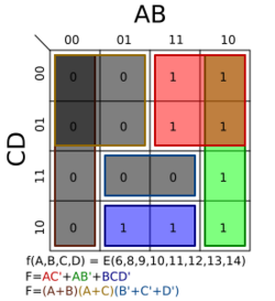
Once the Karnaugh map has been constructed and the adjacent 1s linked by rectangular and square boxes, the algebraic minterms can be found by examining which variables stay the same within each box.
For the red grouping:
- A is the same and is equal to 1 throughout the box, therefore it should be included in the algebraic representation of the red minterm.
- B does not maintain the same state (it shifts from 1 to 0), and should therefore be excluded.
- C does not change. It is always 0, so its complement, NOT-C, should be included. Thus, C should be included.
- D changes, so it is excluded.
Thus the first minterm in the Boolean sum-of-products expression is AC.
For the green grouping, A and B maintain the same state, while C and D change. B is 0 and has to be negated before it can be included. The second term is therefore AB. Note that it is acceptable that the green grouping overlaps with the red one.
In the same way, the blue grouping gives the term BCD.
The solutions of each grouping are combined: the normal form of the circuit is .
Thus the Karnaugh map has guided a simplification of
It would also have been possible to derive this simplification by carefully applying the axioms of Boolean algebra, but the time it takes to do that grows exponentially with the number of terms.
Inverse
The inverse of a function is solved in the same way by grouping the 0s instead.[nb 1]
The three terms to cover the inverse are all shown with grey boxes with different colored borders:
- brown: A B
- gold: A C
- blue: BCD
This yields the inverse:
Through the use of De Morgan's laws, the product of sums can be determined:
Don't cares

Karnaugh maps also allow easier minimizations of functions whose truth tables include "don't care" conditions. A "don't care" condition is a combination of inputs for which the designer doesn't care what the output is. Therefore, "don't care" conditions can either be included in or excluded from any rectangular group, whichever makes it larger. They are usually indicated on the map with a dash or X.
The example on the right is the same as the example above but with the value of f(1,1,1,1) replaced by a "don't care". This allows the red term to expand all the way down and, thus, removes the green term completely.
This yields the new minimum equation:
Note that the first term is just A, not AC. In this case, the don't care has dropped a term (the green rectangle); simplified another (the red one); and removed the race hazard (removing the yellow term as shown in the following section on race hazards).
The inverse case is simplified as follows:
Through the use of De Morgan's laws, the product of sums can be determined:
Race hazards
Elimination
Karnaugh maps are useful for detecting and eliminating race conditions. Race hazards are very easy to spot using a Karnaugh map, because a race condition may exist when moving between any pair of adjacent, but disjoint, regions circumscribed on the map. However, because of the nature of Gray coding, adjacent has a special definition explained above – we're in fact moving on a torus, rather than a rectangle, wrapping around the top, bottom, and the sides.
- In the example above, a potential race condition exists when C is 1 and D is 0, A is 1, and B changes from 1 to 0 (moving from the blue state to the green state). For this case, the output is defined to remain unchanged at 1, but because this transition is not covered by a specific term in the equation, a potential for a glitch (a momentary transition of the output to 0) exists.
- There is a second potential glitch in the same example that is more difficult to spot: when D is 0 and A and B are both 1, with C changing from 1 to 0 (moving from the blue state to the red state). In this case the glitch wraps around from the top of the map to the bottom.


Whether glitches will actually occur depends on the physical nature of the implementation, and whether we need to worry about it depends on the application. In clocked logic, it is enough that the logic settles on the desired value in time to meet the timing deadline. In our example, we are not considering clocked logic.
In our case, an additional term of would eliminate the potential race hazard, bridging between the green and blue output states or blue and red output states: this is shown as the yellow region (which wraps around from the bottom to the top of the right half) in the adjacent diagram.
The term is redundant in terms of the static logic of the system, but such redundant, or consensus terms, are often needed to assure race-free dynamic performance.
Similarly, an additional term of must be added to the inverse to eliminate another potential race hazard. Applying De Morgan's laws creates another product of sums expression for f, but with a new factor of .
2-variable map examples
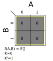
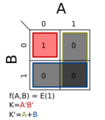
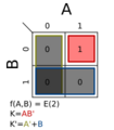
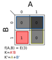
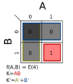
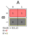
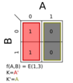
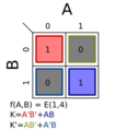
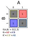
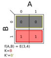
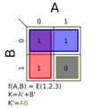
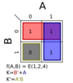
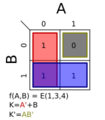
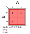
The following are all the possible 2-variable, 2 × 2 Karnaugh maps. Listed with each is the minterms as a function of and the race hazard free (see previous section) minimum equation. A minterm is defined as an expression that gives the most minimal form of expression of the mapped variables. All possible horizontal and vertical interconnected blocks can be formed. These blocks must be of the size of the powers of 2 (1, 2, 4, 8, 16, 32, ...). These expressions create a minimal logical mapping of the minimal logic variable expressions for the binary expressions to be mapped. Here are all the blocks with one field.
A block can be continued across the bottom, top, left, or right of the chart. That can even wrap beyond the edge of the chart for variable minimization. This is because each logic variable corresponds to each vertical column and horizontal row. A visualization of the k-map can be considered cylindrical. The fields at edges on the left and right are adjacent, and the top and bottom are adjacent. K-Maps for four variables must be depicted as a donut or torus shape. The four corners of the square drawn by the k-map are adjacent. Still more complex maps are needed for 5 variables and more.
-
Σm(0); K = 0
-
Σm(1); K = A′B′
-
Σm(2); K = AB′
-
Σm(3); K = A′B
-
Σm(4); K = AB
-
Σm(1,2); K = B′
-
Σm(1,3); K = A′
-
Σm(1,4); K = A′B′ + AB
-
Σm(2,3); K = AB′ + A′B
-
Σm(2,4); K = A
-
Σm(3,4); K = B
-
Σm(1,2,3); K = A' + B′
-
Σm(1,2,4); K = A + B′
-
Σm(1,3,4); K = A′ + B
-
Σm(2,3,4); K = A + B
-
Σm(1,2,3,4); K = 1
Related graphical methods
Related graphical minimization methods include:
- Marquand diagram (1881) by Allan Marquand (1853–1924)[5][6][4]
- Veitch chart (1952) by Edward W. Veitch (1924–2013)[3][4]
- Svoboda chart (1956) by Antonín Svoboda (1907–1980)[7]
- Mahoney map (M-map, designation numbers, 1963) by Matthew V. Mahoney (a reflection-symmetrical extension of Karnaugh maps for larger numbers of inputs)
- Reduced Karnaugh map (RKM) techniques (from 1969) like infrequent variables, map-entered variables (MEV), variable-entered map (VEM) or variable-entered Karnaugh map (VEKM) by G. W. Schultz, Thomas E. Osborne, Christopher R. Clare, J. Robert Burgoon, Larry L. Dornhoff, William I. Fletcher, Ali M. Rushdi and others (several successive Karnaugh map extensions based on variable inputs for a larger numbers of inputs)
- Minterm-ring map (MRM, 1990) by Thomas R. McCalla (a three-dimensional extension of Karnaugh maps for larger numbers of inputs)
See also
- Algebraic normal form (ANF)
- Binary decision diagram (BDD), a data structure that is a compressed representation of a Boolean function
- Espresso heuristic logic minimizer
- List of Boolean algebra topics
- Logic optimization
- Punnett square (1905), a similar diagram in biology
- Quine–McCluskey algorithm
- Reed–Muller expansion
- Venn diagram (1880)
- Zhegalkin polynomial
Notes
- ↑ This should not be confused with the negation of the result of the previously found function.
References
- ↑ 1.0 1.1 "The Map Method for Synthesis of Combinational Logic Circuits". Transactions of the American Institute of Electrical Engineers, Part I: Communication and Electronics 72 (5): 593–599. November 1953. doi:10.1109/TCE.1953.6371932. Paper 53-217. http://philectrosophy.com/documents/The%20Map%20Method%20For%20Synthesis%20of.pdf. Retrieved 2017-04-16. (NB. Also contains a short review by Samuel H. Caldwell.)
- ↑ A new approach to the design of switching circuits. The Bell Laboratories Series (1 ed.). Princeton, New Jersey, USA: D. van Nostrand Company, Inc.. 1962. ISBN 978-0-44201794-1. ark:/13960/t56d6st0q. ISBN 0-44201794-4. OCLC 1036797958. (viii+635 pages) (NB. This book was reprinted by Chin Jih in 1969.)
- ↑ 3.0 3.1 "A Chart Method for Simplifying Truth Functions". Transactions of the 1952 ACM Annual Meeting. ACM Annual Conference/Annual Meeting: Proceedings of the 1952 ACM Annual Meeting (Pittsburgh, Pennsylvania, USA) (New York, USA: Association for Computing Machinery (ACM)): 127–133. 1952-05-03. doi:10.1145/609784.609801.
- ↑ 4.0 4.1 4.2 4.3 4.4 4.5 4.6 Boolean Reasoning - The Logic of Boolean Equations (reissue of 2nd ed.). Mineola, New York: Dover Publications, Inc.. 2012. ISBN 978-0-486-42785-0. [1]
- ↑ 5.0 5.1 "XXXIII: On Logical Diagrams for n terms". The London, Edinburgh, and Dublin Philosophical Magazine and Journal of Science. 5 12 (75): 266–270. 1881. doi:10.1080/14786448108627104. http://www.tandfonline.com/doi/abs/10.1080/14786448108627104. Retrieved 2017-05-15. (NB. Quite many secondary sources erroneously cite this work as "A logical diagram for n terms" or "On a logical diagram for n terms".)
- ↑ 6.0 6.1 "6. Marquand's Machine and Others". Logic Machines and Diagrams (1 ed.). New York, USA: McGraw-Hill Book Company, Inc.. 1958. pp. 104–116. ark:/13960/t5cc1sj6b. ISBN 1-11784984-8. https://archive.org/details/logicmachinesdia227gard. (x+157 pages)
- ↑ 7.0 7.1 "Reference Notations to Chapter 2". Introduction to the Methodology of Switching Circuits (1 ed.). Binghamton, New York, USA: Litton Educational Publishing, Inc. / D. van Nostrand Company. May 1972. p. 84. C4463-000-3. ISBN 0-442-24463-0. (xvi+573+1 pages)
- ↑ Digital Design: Principles & Practices. New Jersey, USA: Prentice Hall. 1994. pp. 48–49, 222. ISBN 0-13-211459-3. (NB. The two page sections taken together say that K-maps are labeled with Gray code. The first section says that they are labeled with a code that changes only one bit between entries and the second section says that such a code is called Gray code.)
- ↑ "Karnaugh Maps – Rules of Simplification". April 1998. http://www.ee.surrey.ac.uk/Projects/Labview/minimisation/karrules.html.
- ↑ "Simplifying Logic Circuits with Karnaugh Maps". The University of Texas at Dallas, Erik Jonsson School of Engineering and Computer Science. September 2015. http://www.utdallas.edu/~dodge/EE2310/lec5.pdf.
- ↑ "Using Karnaugh Maps to Simplify Code". Quantum Rarity. http://www.quantumrarity.com/archives/255.
Further reading
- Contemporary Logic Design. The Benjamin/Cummings Publishing Company. 1998. pp. 70–85. doi:10.1016/0026-2692(95)90052-7. ISBN 0-8053-2703-7. https://archive.org/details/contemporarylogi00katz/page/70.
- "Karnaugh Maps". Switching Theory: Insight Through Predicate Logic. Berlin, Heidelberg, New York: Springer-Verlag. 2004. pp. 57–76. ISBN 3-540-40343-4.
- "3.5. Veitch Diagrams". Logic Design with Integrated Circuits. New York, USA: John Wiley & Sons. 1968. pp. 36–49. https://archive.org/details/logicdesignwithi00wick_0. "[…] a refinement of the Venn diagram in that circles are replaced by squares and arranged in a form of matrix. The Veitch diagram labels the squares with the minterms. Karnaugh assigned 1s and 0s to the squares and their labels and deduced the numbering scheme in common use."
- "Reed-Muller Logic". Logic 101. EE Times. 2006-11-29. Part 3. http://www.eetimes.com/author.asp?section_id=216&doc_id=1274545.
- "Section 2.3". Analysis and Design of Sequential Digital Systems. Macmillan Press. 1977. ISBN 0-33319266-4. https://archive.org/details/AnalysisDesignOfSequentialDigitalSystems/. (146 pages)
- "A modified Karnaugh map technique". IEEE Transactions on Education (IEEE) 48 (1): 206–207. March 2005. doi:10.1109/TE.2004.832879. ISSN 0018-9359. https://ieeexplore.ieee.org/abstract/document/1393123. [2]
- Computer Arithmetic and Verilog HDL Fundamentals (1 ed.). CRC Press. 2008.
- Switching and Finite Automata Theory (3 ed.). Cambridge University Press. 2009. ISBN 978-0-521-85748-2.
- (in de) (Windows/Mac executable or Adobe Flash-capable browser on CD-ROM) KV-Diagramme in der Schaltalgebra - Verknüpfungen, Beweise, Normalformen, schaltalgebraische Umformungen, Anschauungsmodelle, Paradebeispiele (e-book) (1 ed.). Berlin, Germany: viademica Verlag. 2011. ISBN 978-3-939290-08-7. http://www.viademica.de/content/minititel/263.pdf. Retrieved 2022-11-26. [3] (282 pages with 14 animations)
External links
- Detect Overlapping Rectangles, by Herbert Glarner.
- Using Karnaugh maps in practical applications, Circuit design project to control traffic lights.
- K-Map Tutorial for 2,3,4 and 5 variables
- POCKET–PC BOOLEAN FUNCTION SIMPLIFICATION, Ledion Bitincka — George E. Antoniou
- Solve Karnaugh maps online
- Solve k-maps online (from truthtable or boolean-expression)
- K-Map troubleshoot
- "Guide To The K-Map (Karnaugh Map". California State University San Marcos. https://www.csusm.edu/stemsc/handouts/project2_handouts/cs231_karnaugh_maps.pdf.
 |
