Pencil milling
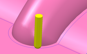
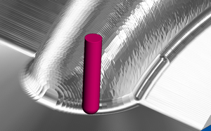
Pencil milling is a cleanup toolpath generated by computer-aided manufacturing (CAM) programs to machine internal corners and fillets with smaller radius tools to remove the remaining material that are inaccessible with larger tools used for previous roughing, semi-finishing, and finishing toolpaths. The name comes from the way that a pencil could naturally be drawn along these corners. It is sometimes called a rolling ball toolpath.
Often a constant step-over passes are derived from single pencil pass to create parallel pencil passes that are very good for cleaning up corners and fillets where excess material remains from a bigger cutter.
Generating pencil toolpaths
There are several alternative algorithms for generating pencil passes.[1] The method most commonly published in the academic literature involves creating tool surface offsets of the model surfaces and intersecting them to find the common line where the cutter would be in contact with two surfaces at once. An example of this implementation uses the ZMap method described by Park, et al.[2]
The industrial method, used in commercial CAM software, differs substantially and works by detecting double-contact points and linking them up into a chain to form a toolpath.[citation needed] A double-contact point is a pair of cutter locations displaced by a tiny distance horizontally, but with a large difference in height or sudden change in contact point. These positions can be located very precisely by binary subdivision, where a cutter location created between a pair of close cutter locations will almost always be continuous with one or the other side.
References
- ↑ "Complete Guide to CAM Toolpaths and Operations for Milling in 2021". 26 July 2021. http://www.cnccookbook.com/CCCAMToolpaths.htm.
- ↑ Pencil curve tracing via virtual digitizing. Mach Impossible Shapes, Kluwer Academic Publishers, 1999, pp. 279–92
 |


