Physics:Cam and groove
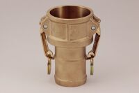
A cam and groove coupling, also called a camlock fitting, is a form of hose coupling. This kind of coupling is popular because it is a simple and reliable means of connecting and disconnecting hoses quickly and without tools.
Standards
Traditionally manufactured to US Military Specification MIL-C-27487, this specification covered the dimensions and machining tolerances, materials, closing torque, part numbers, pressure ratings, finish, inspection procedures and packing requirements. Compliance to this specification ensured inter-changeability of parts from different manufacturers. In 1998, the specification A-A-59326 replaced MIL-C-27487. In Europe the standard BS EN 14420-7 applies as well as the German DIN 2828 standard. Products produced to DIN 2828 are interchangeable with those made to the original MIL-C-27487 but have differences in the hose tail design, thread, part number and other details.[1]
Function
The cams at the end of each lever on the female end align with a circumferential groove on the male end. When the levers are rotated to the locked position, they pull the male end into the female socket, creating a tight seal against a gasket within the female socket. The arms lock into position using over-center geometry, preventing accidental decoupling. Further, lever safety pins are common features for additional security, and female-end "self-locking" levers are also available. Because the groove is cut all the way around the male end, there is no specific rotational alignment necessary to couple, as there would be with threaded connectors, and there is no opportunity for cross-threading. This results in a fast, error-resistant coupling operation. Because the compression between the two fittings is limited by the size of the cams on the end of the levers and the rotation of the levers themselves, there is also no possibility of over- or under-tightening the fitting; the pressure against the sealing gasket is effectively constant from one coupling operation to the next, reducing possibility of leaks.
Materials and uses
Cam and groove fittings are commonly available in several materials, including stainless steel, aluminum, brass, and polypropylene.[2] Because there are no threads to become fouled, cam and groove couplings are popular in moderately dirty environments, such as septic tank pump trucks and chemical or fuel tanker trucks. The system is especially well suited to a situation where frequent changes of hoses are required, such as for petroleum trucks, etc. As examples of industrial application, cam and groove fittings can be used in a system where rapid filling of chemical drums takes place, or by factories that have needs of dye, paint, and ink medium transfers.
Note: Cam and Groove couplings are not recommended for any type of compressed gas service, including steam or air.
Types and sizes
Generally speaking, the most common types of cam and groove coupling are the following types. The letter codes are the common designations, while the roman numeral codes come from the GSA CID A-A-59326[3] standard:
- Type A or Type I: adapter (male end) with female thread, e.g. BSP or NPT
- Type B or Type VII: coupler (female end) with male thread, e.g. BSP or NPT
- Type C or Type VI: coupler with shank (hose barb)
- Type D or Type V: coupler with female thread
- Type E or Type II: adapter with shank
- Type F or Type III: adapter with male thread
- Type IV: adapter with flange, TTMA (Truck Trailer Manufacturer's Association[4])
- Type VIII: coupler with flange, TTMA
- Type DC or Type IX: dust caps (female)
- Type DP or Type X: dust plugs (male) [2]
Apart from these basic types, the hose/pipe connection side of a cam and groove coupler can be of various other types such as with a flange, for butt welding to a container, for truck use with a sight glass, etc.
These couplings are available in the following diameters:
| Inches | Millimetres |
|---|---|
| 1⁄2 | 13 |
| 3⁄4 | 19 |
| 1 | 25 |
| 1 1⁄4 | 32 |
| 1 1⁄2 | 38 |
| 2 | 51 |
| 2 1⁄2 | 64 |
| 3 | 76 |
| 4 | 102 |
| 5 | 127 |
| 6 | 152 |
| 7 | 178 |
| 8 | 203 |
Gallery
See also
- Engineering:Cam (mechanism) – Rotating or sliding component that transmits variable motion to a follower
- Engineering:Lever – Simple machine consisting of a beam pivoted at a fixed hinge
References
- ↑ "Pro Flow FAQ - Camlock Fittings Info - Camlock Couplings Answers". https://www.proflow-dynamics.com/faq.html.
- ↑ Jump up to: 2.0 2.1 "Cam & Groove Couplings and Accessories". http://www.driveproducts.com/wp-content/uploads/2012/04/cam_and_groove_2011_web_CANLDD.pdf.
- ↑ A-A-59326D. "GENERAL SPECIFICATION FOR COUPLING HALVES, QUICK-DISCONNECT, CAM-LOCKING TYPE". General Services Administration. http://everyspec.com/COMML_ITEM_DESC/A-A-59000_A-A-59999/A-A-59326D_37598/.
- ↑ "Home". https://www.trucktrailer.org/.
 |


