Physics:Electrode line
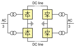
An electrode line is used in some high-voltage direct-current (HVDC) power transmission systems, to connect the converter stations to distant ground electrodes. Many long-distance HVDC systems use sea or ground return for the DC neutral current since this is considerably cheaper than providing a dedicated metallic return conductor on an overhead wire or cable. The ground electrode is separated from the converter station so that current returning through the ground electrode does not cause corrosion of parts of the station in contact with the earth.
Ground connection
The connection to ground requires a specially designed ground electrode (or earth electrode).[1][2] The electrode is usually located several tens of kilometres from the converter station in order to avoid possible problems or corrosion in the converter station grounding system. [3] The electrode line connects the converter station to the grounding electrode. The electrode line can be implemented, depending upon the location of the electrode (onshore or in the sea), as ground cables, as overhead line, or as a combination of ground cable and overhead line.
Bipolar systems
HVDC electrodes are used in most bipolar thyristor-based line-commutated converter (LCC) HVDC transmission systems as a means to improve the reliability of the entire system while also reducing the DC voltage and current ripples. In the event that one of the poles in the bipolar system is faulted, the current path will switch to ground return, thus allowing the system to continue operating at reduced capacity and reducing the possibility that a pole fault will cause a bipolar outage. Usually these ground return paths are only used for very short durations until the faulted pole can be returned to service. The ground current in such schemes can flow in either direction, so the electrodes have to be designed to be reversible, operating either as an anode or cathode. Concerning voltage-source-converter (VSC) HVDC systems, the main reason to use bipolar configurations, especially when the pole-to-pole DC voltages approach 1 MV, is because when one line is faulted in a monopolar HVDC system, the AC phase-to-ground voltages experience peak voltages twice that of normal operation, calling for double the galvanic isolation that is need for normal operation.
Monopolar systems
HVDC electrodes are also used in some monopolar HVDC systems, for example the Italy–Corsica–Sardinia scheme.[4] In such systems the electrode line permanently carries the same current as the high-voltage conductor; however since the ground current is then only unidirectional, one of the electrodes (the cathode) can be of simpler design since corrosion is not a problem for cathode electrodes.
Typical voltages
The operating voltage of the electrode line usually is in the range of approx. 10-20kV (medium voltage range).[5]
See also
- High-voltage direct current
- HVDC converter station
- List of HVDC projects
References
- ↑ Arrillaga, Jos; High Voltage Direct Current Transmission, second edition, Institution of Electrical Engineers, ISBN:0 85296 941 4, 1998, pp190–192.
- ↑ Kimbark, E.W., Direct current transmission, volume 1, Wiley Interscience, 1971, chapter 9.
- ↑ M.V.Bakshi U.A.Bakshi, Elements Of Power Systems, Technical Publications, 2009, ISBN:8184312679 page 12-26
- ↑ Compendium of HVDC schemes, CIGRÉ Technical Brochure No. 003, 1987.
- ↑ Padiyar, K. R. (1990). HVDC Power Transmission Systems: Technology and System Interactions. New Age International. ISBN 9788122401028. https://books.google.com/books?id=gSoDaumDrjoC&q=electrode+line&pg=PA127. Retrieved 29 June 2012.
Further reading
- Cory, B.J., Adamson, C., Ainsworth, J.D., Freris, L.L., Funke, B., Harris, L.A., Sykes, J.H.M., High voltage direct current converters and systems, Macdonald & Co. (publishers) Ltd, 1965.
 |


