Physics:Modular crate electronics

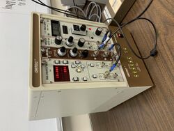
Modular crate electronics are a general type of electronics and support infrastructure commonly used for trigger electronics and data acquisition in particle detectors. These types of electronics are common in such detectors because all the electronic pathways are made by discrete physical cables connecting together logic blocks on the fronts of modules. This allows circuits to be designed, built, tested, and deployed very quickly (in days or weeks) as an experiment is being put together. Then the modules can all be removed and used again when the experiment is done.
A crate is a box (chassis) that mounts in an electronics rack with an opening in the front facing the user. There are rails on the top and bottom of the crate that extend from the open (user) end to the back end of the crate. The back end of the crate contains power and data connectors that modules connect to. Electronics modules slide into the crate along the rails and plug into the power/data connectors at the back. Modules have signal connectors, controls, and lights on their faceplate that are used to interact with other modules.
Some modules just draw power from the backplane connectors and have all of their data inputs and outputs on the front plate. Other modules take inputs or controls to and from the backplane or have their behavior controlled from the backplane. Some types of modules have active circuitry inside them, and act almost as small computers; others are not stateful at all and are only dumb single components.
Types of crate systems
There are number of types of modular crate electronic systems used on particle physics experiments.
RENATRAN
The very first standard for crate electronics was Renatran, which itself was derived from the Esone Standard published in 1964.[1] This standard was in use mainly in France in nuclear research.
The Renatran system consisted of a 5U rackable crate that could accept up to 8 single-width or up to 4 double width plug-in units, with the backplane supplying several power rails, as well as serial and parallel communications between modules, and between the rack and external equipment such as printers and computers. Each plug-in units had the dials, indicators and connectors on the front, and a single screw-mated 24 pin connector (Souriau 8196-17, no longer produced) on the rear to connect to the back-plane. Certain units had additional connectors on the rear, either doubled from the front panel for a more permanent installation, or extra ports for specific purposes, such as daisy chaining counting modules or linking level comparators together. A plug-in unit generally accomplished a single task, such as giving out a clock signal, inverting signal polarity, attenuating or amplifying signals, and more.
NIM
The simplest and one of the earliest crate module standard is the NIM (Nuclear Instrumentation Module) standard. A NIM crate only has power on the backplane, there is no data bus or data connectors. The NIM backplane connector is an irregular arrangement of individual pins into sockets in the crate. NIM modules typically have multiple single logic blocks on the front with both inputs and outputs on the front panel. A typical NIM module might be, say, four discriminators on the front panel, or three AND gates. NIM modules can be hot swapped, since there are no data connectors at the back.
CAMAC
A later crate standard is Computer Automated Measurement and Control, or CAMAC.[2] CAMAC modules are much thinner than NIM modules. The backplane connector of a CAMAC module is a card-edge connector; because of the possibilities of mis-aligning the connectors upon plugin, CAMAC modules are NOT hot swappable. The CAMAC backplane contains a signaling protocol for the crate controller to set the values of registers in modules (for configuration) and to read values of registers (for data acquisition). Due to the slowness of the data communication along the backplane, once FASTBUS was invented, CAMAC modules were mostly used for modules that needed to be computer-configured but not for data acquisition.
FASTBUS
FASTBUS[3] is a crate/module standard developed later than the other two for high-speed parallel data acquisition.[4] Rather than individual components, FASTBUS modules tend to be data acquisition modules with many input connectors on the front, while the stored data is read out on the backplane. The connectors on the back of a FASTBUS module are two parallel pin sockets on the module and pins sticking out of the backplane. The main connector in a FASTBUS crate covers about the bottom 2/3 of the module. There is also an upper connector that consists of pass-through pins to the back side of the backplane; this allows custom modules to be plugged in there.
FASTBUS modules are much taller than the other types of crate modules, so the crates are correspondingly taller.
The FASTBUS backplane is a full data bus where any module could negotiate to be master of the bus to send or receive data.
VME

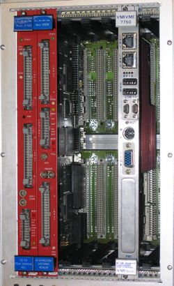
VME (VMEbus) is a bus originally designed to provide an expansion bus for the Motorola 68000 series processor, but it also became a module electronics crate standard. The first editions of VME are three pins wide with pin sockets on the modules and pins on the backplane. In later editions, the physical standard expanded the connectors with two more rows of pins/sockets on the edges for grounding.
VME is mostly designed as a computer bus, so its modules are largely data acquisition modules, not modular electronics.
PXI
PCI eXtensions for Instrumentation (PXI) is one of several modular electronic instrumentation platforms in current use. These platforms are used as a basis for building electronic test equipment, automation systems, and modular laboratory instruments.
AdvancedTCA
The Advanced Telecom Computing Architecture is an open standard for crates. Additionally to power supply and data buses, it also defines a management infrastructure. This allows to perform an array of maintenance task remotely. The standard is governed by the PICMG consortium. [5] The requirements for cards to be used in AdvancedTCA crates, are called Advanced Mezzanine Cards (AMCs) and are specified independently in their own standard.[6]
MicroTCA
MicroTCA is an open, modular standard, based upon AdvancedTCA, but with a smaller form factor. Initially developed for applications in telecommunications, it has since outgrown its initial purpose by developing modules for military, aerospace and scientific use.[7] As AdvancedTCA, it uses AMCs, which makes cards interchangeable between those two.
See also
References
- ↑ Fabre, R.; Gallice, P.; Raoult, N.; Robin, G. (1967). "Renatran Basic Functional Units". IEEE Transactions on Nuclear Science (IEEE) 14 (1): 170–188. doi:10.1109/TNS.1967.4324413. Bibcode: 1967ITNS...14..170F. https://ieeexplore.ieee.org/document/4324413. Retrieved 5 October 2020.
- ↑ "AN INTRODUCTION TO CAMAC". FNAL. http://www-esd.fnal.gov/esd/catalog/intro/introcam.htm. Retrieved 21 September 2013.
- ↑ "AN INTRODUCTION TO FASTBUS". FNAL. Archived from the original on 23 September 2013. https://web.archive.org/web/20130923010620/http://www-esd.fnal.gov/esd/catalog/intro/introfb.htm. Retrieved 21 September 2013.
- ↑ Barsotti, Edward J. (1981). ""FASTBUS" - A DESCRIPTION, A STATUS REPORT, AND A SUMMARY OF ONGOING PROJECTS". FNAL. https://inis.iaea.org/collection/NCLCollectionStore/_Public/13/651/13651016.pdf. Retrieved 22 August 2018.
- ↑ "PICMG | AdvancedTCA". https://www.picmg.org/openstandards/advancedtca/.
- ↑ "PICMG | Advanced MC®". https://www.picmg.org/openstandards/advanced-mezzanine-card/.
- ↑ "PICMG | MicroTCA". https://www.picmg.org/openstandards/microtca/.
 |
