Physics:SRAS

SRAS (spatially resolved acoustic spectroscopy) a non-destructive acoustic microscopy microstructural-crystallographic characterization technique commonly used in the study of crystalline or polycrystalline materials. The technique can provide information about the structure and crystallographic orientation of the material.[1] Traditionally, the information provided by SRAS has been acquired by using diffraction techniques in electron microscopy - such as EBSD. The technique was patented in 2005, EP patent 1910815.
SRAS measures the surface acoustic wave velocity across a specimen, the surface acoustic wave (SAW) velocity is in turn a function of the material state, including parameters such as crystallographic orientation, elastic constants, temperature and stress.
Measurement
In a SRAS measurement, as in most laser ultrasound techniques, two lasers are used, one for the generation of acoustic waves and one for the subsequent detection of these waves. Considering first the generation of acoustic waves, an optical amplitude grating, illuminated by the a short pulse pump laser (typically ~1ns), is imaged onto the sample surface. The incident light is thermoelastically absorbed, creating surface acoustic waves, such as Rayleigh waves. As the laser pulse contains a broad range of frequencies, only the frequencies which match the grating spacing and acoustic velocity of that sample point will be generated. Using a second, continuous wave, laser these surface acoustic waves can then be measured through a number of interferometry techniques. Detection is usually achieved by optical beam deflection.
As Rayleigh waves are non-dispersive the phase velocity of the acoustic wave can be found by
where is the distance between the grating fringes imaged onto the sample surface and is the dominant frequency of the wave packet, found by fast Fourier transform.


As the measurement probes the frequency of the wave packet, which does not change along the propagation length, the measured SAW velocity is determined by only the properties of the specimen at the area where the grating pattern is imaged, unlike more traditional time of flight measurements that are influenced by the sample properties along the propagation length. This makes SRAS robust and immune to the aberrating and scattering effects of the microstructure.

Microstructure imaging
By raster scanning the sample, making measurements at several points across the surface, multi-megapixel images of the SAW velocity can be built up - providing rich microstructural maps. On samples with a good surface finish measurements can be made without averaging, allowing samples to be rapidly scanned. In-theory, means the acquisition rate is limited only by the repetition rate of the pump laser; modern laser repetition rates can exceed 10 kHz. As the measurements do not require a vacuum chamber or acoustic couplant there is little restriction, beyond the limit of scanning stages, to the size of sample which can be interrogated. The elastic anisotropy of most engineering materials means the acoustic response is a function of the loading direction. Hence, a unique velocity map exists for each propagation direction of the SAW direction. It is possible to combine multiple velocity maps to improve contrast between grains.


Orientation mapping

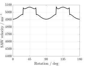
An acoustic slowness surface can be determined for each pixel by propagating the acoustic wave in several directions. Having measured the SAW velocity in multiple directions the challenge is then to convert this information into the measurement of crystallographic orientation. The direct calculation of the orientation from velocity is a difficult problem. However, the numerical calculation of the SAW velocity as a function of SAW velocity is relatively simple, as first outlined by Farnell. Therefore, a database of possible slowness surfaces can be pre-calculated and compared to the measurement values. For each measurement pixel the orientation is given by the orientation of the pre-calculated velocity surface which best matches the measured data. These maps can spatially describe the crystal orientation of the material being interrogated and can be used to examine microtexture and sample morphology. The technique is applicable to any crystal structure, however transverse isotropy means the full orientation cannot be determined in hexagonal materials, such as titanium.[2]
In order to calculate the predicted SAW velocity of the sample, the materials density and elastic constants must be known. Elastic constants are typically measured by ultrasonic techniques such as resonant ultrasound spectroscopy, with well-established values for most common engineering materials. However, it is possible to attempt the full inverse problem to determine both the elastic constants and crystallographic orientation from only the measured SAW velocity.[3]

_plane_Si.png)
From orientation data, a wealth of information can be devised that aids in the understanding of the sample's microstructure and processing history. Recent developments include understanding: the prior texture of parent phases at elevated temperature; the storage and residual deformation after mechanical testing; the population of various microstructural features, including precipitates and grain boundary character.
Single crystal elasticity matrix measuring (SRAS++)
SRAS++ utilises SRAS imaging to provide the raw measurement of single grain velocity surfaces, this is input to a novel inverse solver that mitigates the problem of the inversion being very ill-conditioned, by simultaneously solving for multiple uniquely orientated grains at once in a brute-force approach. This allows simultaneous determination of the elastic constants and crystallographic orientation. Furthermore, this technique has the potential to work on polycrystalline materials with minimal preparation and is capable of high accuracy, with the potential to realise errors in the determination of elastic constants values of less than 1 GPa.


Rough surfaces
Smooth mirror-like surfaces provide specular reflections, allowing easy detection of the acoustic wave. However, as surfaces become rougher the reflections become more diffuse, making detection of the acoustic wave more challenging for two reasons. Firstly, the reflected beam is spread out in a cone, as this cone increases in diameter less light is returned to the system - decreasing detection efficiency. Secondly, the light which is returned to the detector no longer exabits a gaussian intensity, instead the interfering wave fronts create a stochastic speckle pattern. However, many engineering processes impart an optically rough surface, for example additive manufacturing or forging, and there is a desire to make measurements on such components in their 'as manufactured state'. To achieve this, an interferometric technique compatible with rough surfaces is required. For example, a Fabry–Pérot interferometer - which is inherently tolerant to speckle, two-wave mixing - which can adapt to the speckle pattern, or a speckle knife edge detector.[6] With the use of such detection techniques, it is possible to make SRAS measurements on optically rough surfaces.[7]
References
- ↑ Patel, Rikesh; Li, Wenqi; Smith, Richard J.; Sharples, Steve D.; Clark, Matt (November 2017). "Orientation imaging of macro-sized polysilicon grains on wafers using spatially resolved acoustic spectroscopy" (in en). Scripta Materialia 140: 67–70. doi:10.1016/j.scriptamat.2017.07.003.
- ↑ Dryburgh, Paul; Smith, Richard J.; Marrow, Paul; Lainé, Steven J.; Sharples, Steve D.; Clark, Matt; Li, Wenqi (2020-12-01). "Determining the crystallographic orientation of hexagonal crystal structure materials with surface acoustic wave velocity measurements" (in en). Ultrasonics 108. doi:10.1016/j.ultras.2020.106171. ISSN 0041-624X. PMID 32497903.
- ↑ Dryburgh, Paul; Li, Wenqi; Pieris, Don; Fuentes-Domínguez, Rafael; Patel, Rikesh; Smith, Richard J.; Clark, Matt (2022-02-15). "Measurement of the single crystal elasticity matrix of polycrystalline materials" (in en). Acta Materialia 225. doi:10.1016/j.actamat.2021.117551. ISSN 1359-6454. Bibcode: 2022AcMat.22517551D.
- ↑ Dryburgh, Paul; Li, Wenqi; Pieris, Don; Fuentes-Domínguez, Rafael; Patel, Rikesh; Smith, Richard; Clark, Matt (2021-12-07). "Measurement of the single crystal elasticity matrix of polycrystalline materials" (in en). Acta Materialia 225. doi:10.1016/j.actamat.2021.117551. ISSN 1359-6454. Bibcode: 2022AcMat.22517551D.
- ↑ Dryburgh, Paul; Li, Wenqi; Pieris, Don; Fuentes-Domínguez, Rafael; Patel, Rikesh; Smith, Richard; Clark, Matt (2021-12-07). "Measurement of the single crystal elasticity matrix of polycrystalline materials" (in en). Acta Materialia 225. doi:10.1016/j.actamat.2021.117551. ISSN 1359-6454. Bibcode: 2022AcMat.22517551D.
- ↑ Sharpies, S D; Light, R A; Achamfuo-Yeboah, S O; Clark, M; Somekh, M G (2014-06-03). "The SKED: speckle knife edge detector". Journal of Physics: Conference Series 520 (1). doi:10.1088/1742-6596/520/1/012004. ISSN 1742-6588. Bibcode: 2014JPhCS.520a2004S.
- ↑ Patel, Rikesh; Hirsch, Matthias; Dryburgh, Paul; Pieris, Don; Achamfuo-Yeboah, Samuel; Smith, Richard; Light, Roger; Sharples, Steve et al. (2018-10-19). "Imaging Material Texture of As-Deposited Selective Laser Melted Parts Using Spatially Resolved Acoustic Spectroscopy" (in en). Applied Sciences 8 (10): 1991. doi:10.3390/app8101991. ISSN 2076-3417.
 |  |
