Physics:Southwell plot
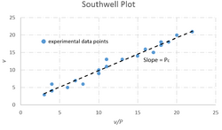
The Southwell plot is a graphical method of determining experimentally a structure's critical load, without needing to subject the structure to near-critical loads.[1] The technique can be used for nondestructive testing of any structural elements that may fail by buckling.[2]
Critical load
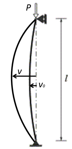
Consider a simply supported beam under a compressive load P. The differential equation of equilibrium is
[math]\displaystyle{ \frac{d^4v}{dx^4} + \alpha^2\frac{d^2}{dx^2}(v-v^o)=0 }[/math], [math]\displaystyle{ \alpha^2=\frac{P}{EI} }[/math]
where vo is the initial deflection, and the boundary conditions are
[math]\displaystyle{ v(0)=v^{' '}(0)=v(L)=v^{' '}(L)=0 }[/math]
Assuming that the deflected shape can be expressed as a Fourier series
[math]\displaystyle{ v^o(x)=\sum_1^\infty v_n^o \sin\frac{n\pi x}{L} }[/math], [math]\displaystyle{ v(x)=\sum_1^\infty v_n \sin\frac{n\pi x}{L} }[/math]
Then after substitution into the differential equation,
[math]\displaystyle{ v(x)=\sum_1^\infty \frac{v_n^o}{P_n / P-1}\sin\frac{n\pi x}{L} }[/math], [math]\displaystyle{ P_n=\frac{n^2\pi^2EI}{L^2} }[/math]
This relates the deflected shape to the initial imperfections and the applied load. Specifically, at x=L/2,
[math]\displaystyle{ v(L/2)=V_1-V_3+V_5+... }[/math], [math]\displaystyle{ V_n=\frac{v_n^o}{P_n/P-1} }[/math]
As P approaches P1, v(L/2) is dominated by V1. Therefore, when P[math]\displaystyle{ \approx }[/math]P1, then the fundamental mode will dominate, resulting in
[math]\displaystyle{ v=V_1=\frac{v_1^o}{P_1/P-1} or \frac{v}{P}=\frac{v}{P_c}+\frac{v_i^o}{P_c} }[/math]
Southwell plots v/P against v and obtains P1=Pcritical=Pc from the slope of the predicted straight line graph.[3]
This analysis was done for a specific point on a simply supported beam, but the concept can be extended to arbitrary structures. With any problem whose mathematical analog is the same fourth order ordinary differential equation as above, with similar boundary conditions, the first eigenvalue of the associated homogeneous problem can be obtained from the slope of the graph. Therefore, a point of large deflection can be chosen, and it does not need to be the center of a simply supported beam.[3]
Applications
Strictly speaking, Southwell's Plot is applicable only to structures with a neutral post-buckling path. Initially created for stability problems in column buckling, the Southwell method has also been used to determine critical loads in frame and plate buckling experiments.
The method is particularly useful for field tests of structures that are likely to be damaged by applying loads near the critical load and beyond, such as reinforced concrete columns or advanced composite materials.[2] The method can also minimize parasitic effects in experiments and give values that are closer to the theoretically expected values. For example, in a real experiment setup it is impossible to reproduce any theoretical boundary condition perfectly. Additionally, the results of compressive tests can be very sensitive to imperfections and the actual boundary conditions. Therefore, the measured critical load during the experiment can be very different from what is predicted.[3]
References
- ↑ Mandal, P., & Calladine, C. (2002). Lateral-torsional buckling of beams and the Southwell plot. International Journal of Mechanical Sciences, 44(12), 2557-2571. doi:10.1016/s0020-7403(02)00192-3
- ↑ 2.0 2.1 Stability Of Structures: Additional Topics. (n.d.). Retrieved November 20, 2016, from http://www.colorado.edu/engineering/CAS/courses.d/Structures.d/IAST.Lect26.d/IAST.Lect26.pdf
- ↑ 3.0 3.1 3.2 Experiment 2.5: Stability of Structures. (n.d.). Retrieved November 20, 2016, from https://mycourses.purdue.edu/bbcswebdav/pid-7803100-dt-content-rid-31348241_1/courses/wl_10033.201710/Lab 5 manual.pdf
 |


