Engineering:Lever escapement
The lever escapement, invented by the English clockmaker Thomas Mudge in 1754 (albeit first used in 1769), is a type of escapement that is used in almost all mechanical watches, as well as small mechanical non-pendulum clocks, alarm clocks, and kitchen timers.
An escapement is a mechanical linkage that delivers impulses to the timepiece's balance wheel, keeping it oscillating back and forth, and with each swing of the balance wheel allows the timepiece's gear train to advance a fixed amount, thus moving the hands forward at a steady rate. The escapement is what makes the "ticking" sound in mechanical watches and clocks.
Invention
The lever escapement was invented by British clockmaker Thomas Mudge around 1754,[1][2] and improved by Abraham-Louis Breguet (1787), Peter Litherland (1791), and Edward Massey (1800). Its modern ("table roller") form was developed by George Savage in the early 1800s.[1][2] Since about 1900 virtually every mechanical watch, alarm clock and other portable timepiece has used the lever escapement.
Advantages
The advantages of the lever are, first, that it is a "detached" escapement; it allows the balance wheel to swing completely free of the escapement during most of its oscillation, except when giving it a short impulse, improving timekeeping accuracy. Second, due to "locking" and "draw" its action is very precise. Third, it is self-starting; if the watch is jarred in use and the balance wheel stops, it will start again. A cheaper and less accurate version of the lever escapement, called the pin pallet escapement, invented by Georges Frederic Roskopf in 1867, is used in clocks and timers.
How it works
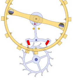
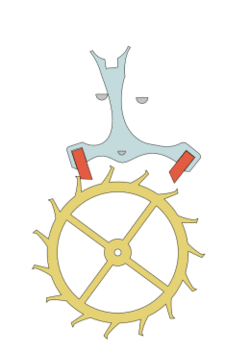
The escape wheel is geared to the watch's wheel train, which applies torque to it from the mainspring. The rotation of the escape wheel is controlled by the pallets. The escape wheel has specially shaped teeth of either ratchet or club form, which interact with the two jewels called the entrance and exit pallets. The escape wheel, except in unusual cases, has 15 teeth and is made of steel. These pallets are attached solidly to the lever, which has at its end a fork to receive the ruby impulse pin of the balance roller which is fixed to the balance wheel shaft. The balance wheel is returned towards its static center position by an attached balance spring (not shown in the diagram). In modern design it is common for the pallet mountings and the fork to be made as a single component. The lever is mounted on a shaft and is free to rotate between two fixed banking pins.
At rest one of the escape wheel teeth will be locked against a pallet. As shown in the diagram, the escape wheel rotates clockwise and the entrance tooth is locked in place against the entrance pallet, the lever held in place by the left banking pin. The impulse pin is located within the lever fork and the balance wheel is near its center position. To get started, the lever fork must receive a small impulse from the anti-clockwise rotation of the balance wheel via the impulse pin (say by being shaken) which rotates the lever slightly clockwise off the left banking pin. This unlocks the entrance pallet allowing the wheel to rotate clockwise.
As the powered escape wheel rotates clockwise, the entrance tooth slides across the sloping impulse plane of the entrance pallet. This turns the pallets about their axis, which places the exit pallet into the path of the rotating escape wheel. Once the entrance tooth leaves the impulse plane of the entrance pallet, the wheel is able to turn a small amount (called the drop) until the exit tooth of the escape wheel lands on the locking face of the exit pallet. The wheel is said to be locked on the exit pallet. From the release from the entrance pallet to this point, the escape wheel will have turned through exactly one half of the 24 degree angle between two teeth.
The impulse received by the entrance pallet as the tooth moves over the impulse face is transferred by the lever to the balance wheel via the ruby impulse pin on the roller of the balance wheel. The lever moves until it rests against the right banking pin; it is held in this position by the force of the exit tooth against the exit pallet jewel (called the draw). This means that in order to unlock the wheel it must be turned backwards by a small amount, which is done by the return momentum of the balance wheel via the impulse pin.
After the exit tooth locks, the balance wheel rotates anti-clockwise, free of interference from the escapement until the hairspring pulls it back clockwise, and the impulse pin re-enters the fork. This will unlock the escapement, releasing the escape wheel so that the exit tooth can slide over the impulse plane of the exit pallet, which transfers a clockwise impulse to the balance wheel's impulse pin via the lever fork, while pushing the lever up against the left banking pin. The escape wheel drops again until the entrance tooth locks on the entrance pallet now being held in place by the left banking pin via the lever. The balance wheel continues clockwise, again free from interference until it is pulled back by the hairspring to the center position. The cycle then starts again.
Each back and forth movement of the balance wheel from and back to its center position corresponds to a drop of one tooth (called a beat). A typical watch lever escapement beats at 18,000 or more beats per hour. Each beat gives the balance wheel an impulse, so there are two impulses per cycle. Despite being locked at rest most of the time, the escape wheel rotates typically at an average of 10 rpm or more.
The origin of the "tick tock" sound is caused by this escapement mechanism. As the balance wheel rocks back and forth, the ticking sound is heard.[3]
Draw
The reliability of the modern lever escapement depends upon draw; the pallets are angled so that the escape wheel must recoil a small amount during the unlocking. The draw holds the lever against the banking pins during the detached portion of the operating cycle. Draw angle is typically about 11-15 degrees to the radial.
Early lever escapements lacked draw (indeed some makers considered it injurious as a cause of extra friction in unlocking); as a result a jolt could result in the escapement unlocking.
Lever watch movement
Most modern mechanical watches are jeweled lever watches, using synthetic ruby or sapphire jewels for the high-wear areas of the watch.
Pin pallet escapement
A cheaper, less accurate version of the lever escapement is used in alarm clocks, kitchen timers, mantel clocks and, until the late 1970s, cheap watches, called the Roskopf, pin-lever, or pin-pallet escapement after Georges Frederic Roskopf, who invented it in 1867. It functions similarly to the lever, except that the lever pallet jewels are replaced by vertical metal pins. In a lever escapement, the pallets have two angled faces, the locking face and the impulse face, which must be carefully adjusted to the correct angles. In the pin pallet escapement, these two faces are designed into the shape of the escape wheel teeth instead, eliminating complicated adjustments. The pins are located symmetrically on the lever, making beat adjustment simpler. Watches that used these escapements were called pin lever watches, and have been superseded by cheap quartz watches.
Future directions
One recent trend in escapement design is the use of new materials, many borrowed from the semiconductor fabrication industry.[4] A problem with the lever escapement is friction. The escape wheel tooth slides along the face of the pallet, causing friction, so the pallets and teeth must be lubricated. The oil eventually thickens, causing inaccuracy, and requiring cleaning and reoiling of the movement about every 4 years. A solution is to make the escape wheel and other parts out of harder materials than steel, eliminating the need for lubrication. Materials being tried include silicon, nickel phosphorus, diamond, and diamond-on-silicon. Ulysse Nardin in 2001, Patek Philippe in 2005, and Zenith in 2013 introduced watches with silicon escape wheels.
See also
- Anchor escapement
- Co-axial escapement
References
- ↑ 1.0 1.1 Britten, Frederick James (1899). Old Clocks and Watches and their Makers. London: B. T. Batsford. pp. 349–350. https://books.google.com/books?id=4e_eAAAAMAAJ&q=%22lever+escapement%22+history+massey&pg=PA350.
- ↑ 2.0 2.1 Glasgow, David (1885). Watch and Clock Making. London: Cassel & Co.. pp. 180-183. https://archive.org/details/watchclockmaking00glas.
- ↑ "Westime | Fun & Educational | What Makes a Watch Tick?". http://www.westime.com/funeduc_tick.php.
- ↑ Treffry, Timothy (2006-05-30). "Heart of Lightness". QP Magazine (London) 15 (24): 86–91. http://qp.granularit.com/media/39077/Heart_of_Lightness_Silicon.pdf. Retrieved 2018-03-20.
External links
- An Analysis of the Lever Escapement, by H. R. Playtner, 1910, from Project Gutenberg
 |


