Engineering:Binary decoder
This article needs additional citations for verification. (May 2009) (Learn how and when to remove this template message) |
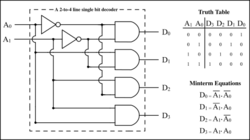
In digital electronics, a binary decoder is a combinational logic circuit that converts binary information from the n coded inputs to a maximum of 2n unique outputs. They are used in a wide variety of applications, including instruction decoding, data multiplexing and data demultiplexing, seven segment displays, and as address decoders for memory and port-mapped I/O.
There are several types of binary decoders, but in all cases a decoder is an electronic circuit with multiple input and multiple output signals, which converts every unique combination of input states to a specific combination of output states. In addition to integer data inputs, some decoders also have one or more "enable" inputs. When the enable input is negated (disabled), all decoder outputs are forced to their inactive states.
Depending on its function, a binary decoder will convert binary information from n input signals to as many as 2n unique output signals. Some decoders have less than 2n output lines; in such cases, at least one output pattern may be repeated for different input values.
A binary decoder is usually implemented as either a stand-alone integrated circuit (IC) or as part of a more complex IC. In the latter case the decoder may be synthesized by means of a hardware description language such as VHDL or Verilog. Widely used decoders are often available in the form of standardized ICs.
Types of decoders
1-of-n decoder
A 1-of-n binary decoder has n output bits. This type of decoder asserts exactly one of its n output bits, or none of them, for every integer input value. The "address" (bit number) of the activated output is specified by the integer input value. For example, output bit number 0 is selected when the integer value 0 is applied to the inputs.
Examples of this type of decoder include:
- A 3-to-8 line decoder activates one of eight output bits for each input value from 0 to 7 — the range of integer values that can be expressed in three bits. Similarly, a 4-to-16 line decoder activates one of 16 outputs for each 4-bit input in the integer range [0,15].
- A BCD to decimal decoder has ten output bits. It accepts an input value consisting of a binary-coded decimal integer value and activates one specific, unique output for every input value in the range [0,9]. All outputs are held inactive when a non-decimal value is applied to the inputs.
- A demultiplexer is a 1-of-n binary decoder that is used to route a data bit to one of its n outputs while all other outputs remain inactive.
Code translator
Code translators differ from 1-of-n decoders in that multiple output bits may be active at the same time. An example of this is a seven-segment decoder, which converts an integer into the combination of segment control signals needed to display the integer's value on a seven-segment display digit.
One variant of seven-segment decoder is the BCD to seven-segment decoder, which translates a binary-coded decimal value into the corresponding segment control signals for input integer values 0 to 9. This decoder function is available in standard ICs such as the CMOS 4511.
Binary to Unary Decoder
A binary to unary decoder converts each binary value to its associated unary representation. Unlike the 1-of-n (one-hot) decoder, multiple output bits can be asserted for each input value. These decoders can be used in DACs where each bit is equally weighted, and circuits that require a binary mask or window.[1]
See also
- Multiplexer
- One-hot, the format of the 1-of-n decoder's output (or the unencoded output of a ring counter)
- Priority encoder
- Sum-addressed decoder
References
- ↑ "Binary to unary decoder for a video digital to analog converter" US patent 5313300A, issued 1992-08-10
 |


