Software:Stateflow
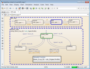
 Control logic for an automatic transmission system | |
| Developer(s) | MathWorks |
|---|---|
| Stable release | R2018b
/ September 12, 2018 |
| Preview release | R2018b
/ June 14, 2018 |
| Operating system | Windows, macOS, Linux[1] |
| Platform | x64 |
| Type | Application software |
| License | Proprietary |
| Website | Stateflow product page |
Stateflow (developed by MathWorks) is a control logic tool used to model reactive systems via state machines and flow charts within a Simulink model. Stateflow uses a variant of the finite-state machine notation established by David Harel, enabling the representation of hierarchy, parallelism and history within a state chart.[2][3] Stateflow also provides state transition tables and truth tables.
Common uses
Stateflow is generally used to specify the discrete controller in the model of a hybrid system where the continuous dynamics (i.e., the behavior of the plant and environment) are specified using Simulink.[4][5]
Specific applications for Stateflow include:
- Mode logic, where each discrete mode of a system is represented by a state[6]
- Fault management, where the Stateflow chart is used to control how the system responds to faults and failures within a system[7]
- Task scheduling, where the Stateflow chart is used to schedule when specific tasks occur, either within the Stateflow chart or within the overall Simulink model[8]
Extensions
A number of MathWorks and third-party tools can be used with Stateflow to validate the design and generate code. For example, Simulink Verification and Validation, a MathWorks tool, can be used to check for requirements traceability and model coverage analysis. Other add-on code generation tools can be used to automatically generate C, C++, HDL, and PLC code for implementation on embedded systems.
References
- ↑ MathWorks - Stateflow - Requirements
- ↑ MATLAB Tech Talks on the basics and usage of state machines
- ↑ Simulation of Hybrid Systems Using Stateflow
- ↑ Gregoire Hamon; John Rushby. "An Operational Semantics for Stateflow". Presented at Fundamental Approaches to Software Engineering (FASE) Barcelona, Spain, March 2004 (SRI International Computer Science Laboratory). http://www.csl.sri.com/users/rushby/papers/fase04.pdf.
- ↑ Orion GN&C MATLAB/Simulink/Stateflow Standards
- ↑ A. Tiwari. Formal Semantics and Analysis Methods for Simulink Stateflow Models. SRI International Computer Science Laboratory. http://www.csl.sri.com/users/tiwari/papers/stateflow.pdf.
- ↑ Requirements-Based Testing in Aircraft Control Design
- ↑ Embedded Coder Robot NXT Modeling Tips

