Engineering:Pumpjack
A pumpjack is the overground drive for a reciprocating piston pump in an oil well.[1]
It is used to mechanically lift liquid out of the well if there is not enough bottom hole pressure for the liquid to flow all the way to the surface. The arrangement is often used for onshore wells. Pumpjacks are common in oil-rich areas.
Depending on the size of the pump, it generally produces 5 to 40 litres (1 to 9 imp gal; 1.5 to 10.5 US gal) of liquid at each stroke. Often this is an emulsion of crude oil and water. Pump size is also determined by the depth and weight of the oil to remove, with deeper extraction requiring more power to move the increased weight of the discharge column (discharge head).
A beam-type pumpjack converts the rotary motion of the motor to the vertical reciprocating motion necessary to drive the polished-rod and accompanying sucker rod and column (fluid) load. The engineering term for this type of mechanism is a walking beam. It was often employed in stationary and marine steam engine designs in the 18th and 19th centuries.
Names
A pumpjack is also called a beam pump, walking beam pump, horsehead pump, nodding donkey pump (donkey pumper), rocking horse pump, grasshopper pump, sucker rod pump, dinosaur pump, Big Texan pump, thirsty bird pump, hobby horse, or just pumping unit.[2]
Above ground
In the early days, pumpjacks worked by rod lines running horizontally above the ground to a wheel on a rotating eccentric in a mechanism known as a central power.[3] The central power, which might operate a dozen or more pumpjacks, would be powered by a steam or internal combustion engine or by an electric motor. Among the advantages of this scheme was only having one prime mover to power all the pumpjacks rather than individual motors for each. However, among the many difficulties was maintaining system balance as individual well loads changed.
Modern pumpjacks are powered by a prime mover. This is commonly an electric motor, but internal combustion engines are used in isolated locations without access to electricity, or, in the cases of water pumpjacks, where three-phase power is not available (while single phase motors exist at least up to 60 horsepower or 45 kilowatts,[4] providing power to single-phase motors above 10 horsepower or 7.5 kilowatts can cause powerline problems,[5] and many pumps require more than 10 horsepower). Common off-grid pumpjack engines run on natural gas, often casing gas produced from the well, but pumpjacks have been run on many types of fuel, such as propane and diesel fuel. In harsh climates, such motors and engines may be housed in a shack for protection from the elements. Engines that power water pumpjacks often receive natural gas from the nearest available gas grid.
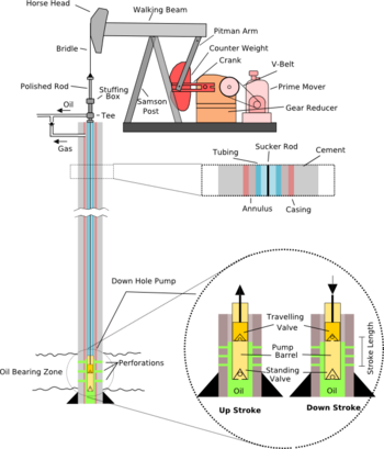
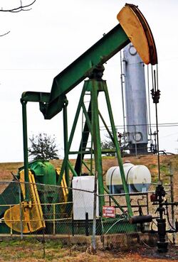
The prime mover runs a set of pulleys to the transmission, often a double-reduction gearbox, which drives a pair of cranks, generally with counterweights installed on them to offset the weight of the heavy rod assembly. The cranks raise and lower one end of an I-beam which is free to move on an A-frame. On the other end of the beam is a curved metal box called a horse head or donkey head, so named due to its appearance. A cable made of steel—occasionally, fibreglass—, called a bridle, connects the horse head to the polished rod, a piston that passes through the stuffing box.
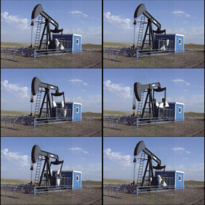
The cranks themselves also produce counterbalance due to their weight, so on pumpjacks that do not carry very heavy loads, the weight of the cranks themselves may be enough to balance the well load. File:Pumpjack.webm Sometimes, however, crank-balanced units can become prohibitively heavy due to the need for counterweights. Lufkin Industries offer "air-balanced" units, where counterbalance is provided by a pneumatic cylinder charged with air from a compressor, eliminating the need for counterweights.
The polished rod has a close fit to the stuffing box, letting it move in and out of the tubing without fluid escaping. (The tubing is a pipe that runs to the bottom of the well through which the liquid is produced.) The bridle follows the curve of the horse head as it lowers and raises to create a vertical or nearly-vertical stroke. The polished rod is connected to a long string of rods called sucker rods, which run through the tubing to the down-hole pump, usually positioned near the bottom of the well.
Down-hole
At the bottom of the tubing is the down-hole pump. This pump has two ball check valves: a stationary valve at bottom called the standing valve, and a valve on the piston connected to the bottom of the sucker rods that travels up and down as the rods reciprocate, known as the traveling valve. Reservoir fluid enters from the formation into the bottom of the borehole through perforations that have been made through the casing and cement (the casing is a larger metal pipe that runs the length of the well, which has cement placed between it and the earth; the tubing, pump, and sucker rod are all inside the casing).
When the rods at the pump end are travelling up, the traveling valve is closed and the standing valve is open (due to the drop in pressure in the pump barrel). Consequently, the pump barrel fills with the fluid from the formation as the traveling piston lifts the previous contents of the barrel upwards. When the rods begin pushing down, the traveling valve opens and the standing valve closes (due to an increase in pressure in the pump barrel). The traveling valve drops through the fluid in the barrel (which had been sucked in during the upstroke). The piston then reaches the end of its stroke and begins its path upwards again, repeating the process.
Often, gas is produced through the same perforations as the oil. This can be problematic if gas enters the pump, because it can result in what is known as gas locking, where insufficient pressure builds up in the pump barrel to open the valves (due to compression of the gas) and little or nothing is pumped. To preclude this, the inlet for the pump can be placed below the perforations. As the gas-laden fluid enters the well bore through the perforations, the gas bubbles up the annulus (the space between the casing and the tubing) while the liquid moves down to the standing valve inlet. Once at the surface, the gas is collected through piping connected to the annulus.
Water well pumpjacks
Pumpjacks can also be used to drive what would now be considered old-fashioned hand-pumped water wells. The scale of the technology is frequently smaller than for an oil well, and can typically fit on top of an existing hand-pumped well head. The technology is simple, typically using a parallel-bar double-cam lift driven from a low-power electric motor, although the number of pumpjacks with stroke lengths 54 inches (1.4 m) and longer being used as water pumps is increasing. A short video recording of such a pump in action can be viewed on YouTube.[6]
Although the flow rate for a water well pumpjack is lower than that from a jet pump and the lifted water is not pressurised, the beam pumping unit has the option of hand pumping in an emergency, by hand-rotating the pumpjack cam to its lowest position, and attaching a manual handle to the top of the wellhead rod. In larger pumpjacks powered by engines, the engine can run off fuel stored in a reservoir or from natural gas delivered from the nearest gas grid. In some cases, this type of pump consumes less power than a jet pump and is, therefore, cheaper to run.
See also
References
- ↑ "Old Stuff from the Oil Fields - Pumping Jacks". http://www.sjvgeology.org/old_stuff/pumpjacks.html.
- ↑ "Colorful "pumpjack," a type of small oil pump that's a common sight in West Texas, along U.S. 83 near the town of Winters in Runnels County, Texas". Library of Congress. 2014-03-07. https://www.loc.gov/resource/highsm.27153/.
- ↑ "Oil History: The Central Power". http://www.petroleumhistory.org/OilHistory/pages/Central%20Power/centralpower.html.
- ↑ "Single Phase Motors". http://www.meridiumpower.ca/A/a_1.html.
- ↑ "Options Beyond Three-Phase For Serving Remote Motor Loads". https://www.rerc.org/pdf_files/three_phase_options.pdf.
- ↑ Pumping unit on YouTube
External links
- All Pumped Up – Oilfield Technology, The American Oil & Gas Historical Society, updated October 2014
nv:Chidí bikʼáh tr:Atbaşı
 |


