Engineering:Riser card

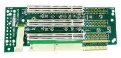
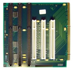
A riser card is a printed circuit board that gives a computer motherboard the option for additional expansion cards to be added to the computer.[1]
Usage
A riser is usually connected to the mainboard's slot through an edge connector, though some, such as NLX and Next Unit of Computing Extreme, instead are plugged into an edge connector on the mainboard itself. In general, the main purpose is to change the orientation of the expansion cards such that they fit a limited space within casing. [2]
Riser cables
Riser cables are an evolution of riser cards utilizing improved specifications (specifically the use of PCI Express) and better materials, which allows further distances of data transmission and greater orientation flexibility than traditional riser cards. These cables use a Riser Card PCB and an edge connector on each side of the cable, with a copper alloy surrounded by a plastic insulator that allows for the further data transmission distances.[3]
Such cables are now commonly used in modern household gaming PC's to allow for different positioning of PCI Express Cards and GPU cards in a computer case. This allows for customization and the addition of additional parts to suit the creator or builders needs. They can additionally be installed into vertical brackets to function similarly to a riser card, but with further flexibility. They are also used in small-form-factor PC's to allow for a GPU to be positioned behind a computer motherboard. [4]
Specifications
There are only a few specified standards in regards to riser designs. Most use PCI Express edge connectors for data transfer. This allows for maximum data transfer speeds of 32 GB/s when using PCIe 4.0, along with 75W of power to be delivered from the host device.[4] Other specifications used for these cards include ExpressCard and PCI-X.[5]
Applications
Riser cards have applications in both industrial and consumer spaces.[2]
Industrial
In servers, height for expansion cards is limited by rack units. A unit (U) is the traditional measurement used for server height. One server unit is equal to 1.75", 2U servers are 3.5", and so forth. Traditional 1U riser cards each fit 1 PCI slot, and 2U riser cards can fit 2 or 3 PCI slots, depending on whether they obstruct access to any PCI-E slots. [2]
Consumer
In small-form-factor (SFF) computers built by computer enthusiasts, PCI-E riser cards are used in a similar sense to a server application. They are used to sandwich a graphics card closer to a computer motherboard and are made to the same heights as server units for most applications. The additional flexibility afforded by PCI Express can allow for a GPU to be placed "behind" the mainboard, allowing space-efficient orientation without limiting the GPU's airflow.[2]
See also
- Daughterboard
References
- ↑ "What is a riser card?". 2018-11-13. https://www.computerhope.com/jargon/r/risecard.htm.
- ↑ 2.0 2.1 2.2 2.3 "Riser Cards". https://www.arrow.com/en/categories/computer-products/applied-computing-and-embedded-systems/riser-cards.
- ↑ "Inwin PCI-E Riser Cable Specifications". https://www.in-win.com/en/spare-parts/pci-e-riser-cable#:~:text=InWin's%20PCI%2DE%203.0%20X16,any%20chassis%20on%20the%20market..
- ↑ 4.0 4.1 "Information About PCIe® Riser Cable and Extender Compatibility with PCIe® Gen 4.0 Desktop Systems". https://www.amd.com/en/support/kb/faq/pa-270.
- ↑ "Riser and Daughter Card Implementations". https://www.globalspec.com/reference/72718/203279/riser-and-daughter-card-implementations.
External links
 |


